Condensate Recovery

Contents
Sizing Condensate Return Lines
A guide to sizing condensate lines to and from steam traps, including examples and calculations using the condensate pipe sizing chart.
Sizing Condensate Return Lines
The four main types of condensate line, as mentioned in Module 14.2, are shown in Table 14.3.1:
Table 14.3.1 The four basic types of condensate line
| Type of condensate line | Condensate line is sized to carry the following |
| Drain lines to trap | Condensate |
| Discharge lines from traps | Flash steam |
| Common return lines | Flash steam |
| Pumped return lines | Condensate |
Sizing of all condensate lines is a function of:
- Pressure - The difference in pressure between one end of the pipe and the other. This pressure difference may either promote flow, or cause some of the condensate to flash to steam.
- Quantity - The amount of condensate to be handled.
- Condition - Is the condensate predominately liquid or flash steam?
With the exception of pumped return lines which will be discussed in Module 14.4, the other three main types of condensate line and their sizing, will be covered in this Module.
Sizing drain lines to traps
It should not be assumed that the drain line (and trap) should be the same size as the plant outlet connection. The plant may operate at a number of different operating pressures and flowrates, especially when it is temperature controlled. However, once the trap has been correctly sized, it is usually the case that the drain line will be the same size as the trap inlet connection, (see Figure 14.3.1).

Regarding the conditions inside the drain line, as there is no significant pressure drop between the plant and the trap, no flash steam is present in the pipe, and it can be sized to carry condensate only.
When sizing the drain line, the following will need consideration:
- The condensing rate of the equipment being drained during full-load.
- The condensing rate of the equipment at start-up.
At plant start-up, the condensing rate can be up to three times the running load – this is where the temperature difference between the steam and colder product is at its maximum.
The drain line, trap, and discharge line also have to carry the air that is displaced by the incoming steam during this time.
The sizing routine for the steam trap will have to consider both of these variables, however, in general:
- For steam mains drainage, the condensate load for each drain trap is typically 1% of the steam capacity of the main based on drain points at 50 m intervals, and with good insulation.
For most drain points, sizing the trap to pass twice the running load at the working pressure (minus any backpressure) will allow it to cope with the start-up load.
- On constant steam pressure processes such as presses, ironers, unit heaters, radiant panels and boiling pans, sizing the traps on approximately twice the running load at the working pressure (less any backpressure) will provide sufficient capacity to cope with the start-up load.
- On temperature controlled applications, the steam pressure, the plant turndown, the set temperature and steam trap location need to be considered in detail, and the trap needs to be sized to cater for both the full and minimum load conditions. If these conditions are not known it is recommended that the steam trap be sized on 3 x the running load at the running differential pressure. This should satisfy the start-up condition and provide proper drainage at minimum loads.
When the trap is sized in this way, it will also cater for the start-up load. Consequently, if the drain line to the trap is sized on the trap size, it will never be undersized.
For practical purposes, where the drain line is less than 10 m, it can be the same pipe size as the steam trap selected for the application. Drain lines less than 10 m long can also be checked against Appendix 14.3.1 and a pipe size should be selected which results in a pressure loss at maximum flowrate of not more than 200 Pa per metre length, and a velocity not greater than 1.5 m/s. Table 14.3.2 is an extract from Appendix 14.3.1.
On longer drain lines (over 10 m), the pressure loss at maximum flowrate should not be more than 100 Pa/m, and a velocity not greater than 1 m/s.
Table 14.3.2 Flow of water in heavy steel pipes
| Flowrate | Capacity kg/h | ||||||||||
| Pipe size Ø | 15 mm |
20 mm |
25 mm |
32 mm |
40 mm |
50 mm |
65 mm |
80 mm |
100 mm |
||
| Pa/m | mbar/m | <0.15 m/ s | 0.15 m/s | 0.3 m/s | |||||||
| 90 | 0.9 | 173 | 403 | 745 | 1627 | 2488 | 4716 | 9612 | 14940 | 30240 | 1.0 m/s |
| 92.5 | 0.925 | 176 | 407 | 756 | 1652 | 2524 | 4788 | 9756 | 15156 | 30672 | |
| 95 | 0.95 | 176 | 414 | 767 | 1678 | 2560 | 4860 | 9900 | 15372 | 31104 | |
| 97.5 | 0.975 | 180 | 421 | 778 | 1699 | 2596 | 4932 | 10044 | 15552 | 31500 | |
| 100 | 1 | 184 | 425 | 788 | 1724 | 2632 | 5004 | 10152 | 15768 | 31932 | |
| 120 | 1.2 | 202 | 472 | 871 | 1897 | 2898 | 5508 | 11196 | 17352 | 35100 | |
| 140 | 1.4 | 220 | 511 | 943 | 2059 | 3143 | 5976 | 12132 | 18792 | 38160 | |
| 160 | 1.6 | 234 | 547 | 1015 | 2210 | 3373 | 6408 | 12996 | 20160 | 40680 | |
| 180 | 1.8 | 252 | 583 | 1080 | 2354 | 3589 | 6804 | 13824 | 21420 | 43200 | 1.5 m/s |
| 200 | 2 | 266 | 619 | 1141 | 2488 | 3780 | 7200 | 14580 | 22644 | 45720 | |
| 220 | 2.2 | 281 | 652 | 1202 | 2617 | 3996 | 7560 | 15336 | 23760 | 47880 | |
| 240 | 2.4 | 288 | 680 | 1256 | 2740 | 4176 | 7920 | 16056 | 24876 | 50400 | |
| 260 | 2.6 | 306 | 713 | 1310 | 2855 | 4356 | 8244 | 16740 | 25920 | 52200 | |
| 280 | 2.8 | 317 | 742 | 1364 | 2970 | 4536 | 8568 | 17388 | 26928 | 54360 | |
| 300 | 3 | 331 | 767 | 1415 | 3078 | 4680 | 8892 | 18000 | 27900 | 56160 | |
Example 14.3.1
An item of plant, using steam at constant pressure, condenses 470 kg of steam an hour at full-load. The pipework between the plant item and the steam trap has an equivalent length of 2 m.
Determine the size of pipe to be used.
Revised load allowing for start-up = 470 kg /h x 2 = 940 kg /h.
As the pipe length is less than 10 metres, the maximum allowable pressure drop is 200 Pa/m.
Using Table 14.3.1, by looking across from 200 Pa/m it can be seen that a 25 mm pipe has a capacity of 1 141 kg /h, and would therefore be suitable for the expected starting load of 940 kg /h.
Checking further up the 25 mm column, it can be seen that a flowrate of 940 kg /h will incur an actual pressure drop of just less than 140 Pa/m flowing through a 25 mm pipe.
Sizing discharge lines from traps
The section of pipeline downstream of the trap will carry both condensate and flash steam at the same pressure and temperature. This is referred to as two-phase flow, and the mixture of liquid and vapour will have the characteristics of both steam and water in proportion to how much of each is present. Consider the following example.
Example 14.3.2
An item of plant uses steam at a constant 4 bar g pressure. A mechanical steam trap is fitted, and condensate at saturation temperature is discharged into a condensate main working at 0.5 bar g.
Determine the proportions by mass, and by volume, of water and steam in the condensate main.
Part 1 - Determine the proportions by mass
From steam tables:

Clearly, if 7.9% is flashing to steam, the remaining 100 – 7.9 = 92.1% of the initial mass flow will remain as water.
Part 2 - Determine the proportions by volume
Based on an initial mass of 1 kg of condensate discharged at 4 bar g saturation temperature, the mass of flash steam is 0.079 kg and the mass of condensate is 0.921 kg (established from Part 1).
Water:
The density of saturated water at 0.5 bar g is 950 kg/m3,

From this, it follows that the two-phase fluid in the trap discharge line will have much more in common with steam than water, and it is sensible to size on reasonable steam velocities rather than use the relatively small volume of condensate as the basis for calculation. If lines are undersized, the flash steam velocity and backpressure will increase, which can cause waterhammer, reduce the trap capacity, and flood the process.
Steam lines are sized with attention to maximum velocities. Dry saturated steam should travel no faster than 40 m/s. Wet steam should travel somewhat slower (15 to 20 m/s) as it carries moisture which can otherwise have an erosive and damaging effect on fittings and valves.
Trap discharge lines can be regarded as steam lines carrying very wet steam, and should be sized on similarly low velocities.
Condensate discharge lines from traps are notoriously more difficult to size than steam lines due to the two-phase flow characteristic. In practice, it is impossible (and often unnecessary) to determine the exact condition of the fluid inside the pipe.
Although the amount of flash steam produced (see Figure 14.3.2) is related to the pressure difference across the trap, other factors will also have an effect.
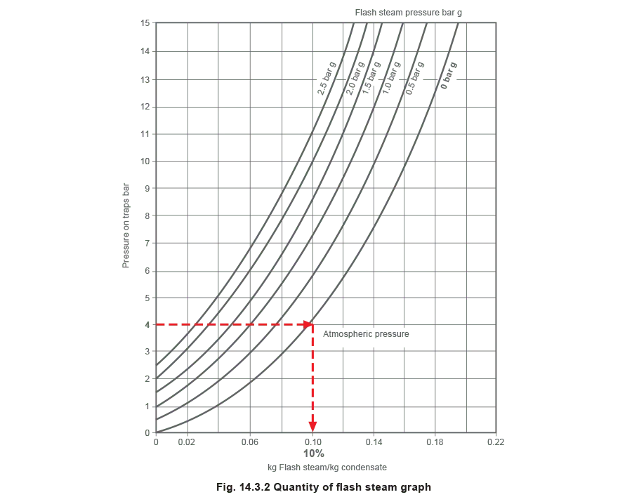
Factors having a bearing on two-phase flow inside a pipe, include:
- If the condensate on the upstream side of the trap is cooler than the saturation temperature (for example: a thermostatic steam trap is used), the amount of flash steam after the trap is reduced. This can reduce the size of the line required.
- If the line slopes down from the trap to its termination, the slope will have an effect on the flow of condensate, but to what magnitude, and how can this be quantified?
- On longer lines, radiation losses from the line may condense some of the flash steam, reducing its volume and velocity, and there may be a case for reducing the line size. But at what point should it be reduced and by how much?
- If the discharge line lifts up to an overhead return line, there will be times when the lifting line will be full of cool condensate, and times when flash steam from the trap may evaporate some or all of this condensate. Should the rising discharge line be sized on flash steam velocity or the quantity of condensate?
- Most processes operate some way below their full-load condition for most of their running cycle, which reduces flash steam for most of the time. The question therefore arises: is there a need for the system to be sized on the full-load condition, if the equipment permanently runs at a lower running load?
- On temperature controlled plant, the pressure differential across the trap will itself change depending on the heat load. This will affect the amount of flash steam produced in the line.
Recommendations on trap discharge lines
Because of the number of variables, an exact calculation of line size would be complex and probably inaccurate. Experience has shown that if trap discharge lines are sized on flash steam velocities of 15 to 20 m/s, and certain recommendations are adhered to, few problems will arise.
Recommendations:
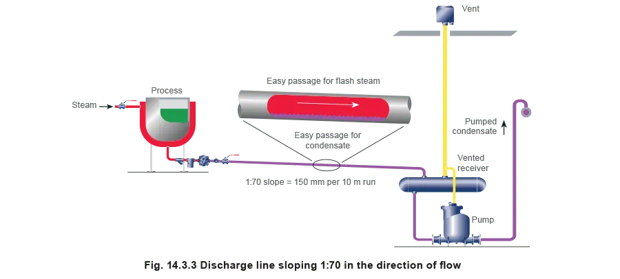
- Correctly sized trap discharge lines which slope in the direction of flow and are open-ended or vented at a receiver, will be non-flooded and allow flash steam to pass unhindered above the condensate (Figure 14.3.3). A minimum slope of 1 in 70 (150 mm drop every 10 m) is recommended. A simple visual check will usually confirm if the line is sloping - if no slope is apparent it is not sloping enough!
2. If it is unavoidable, non-pumped rising lines (Figure 14.3.4) should be kept as short as possible and fitted with a non-return valve to stop condensate falling back down to the trap. Risers should discharge into the top of overhead return lines. This stops condensate draining back into the riser from the return main after the trap has discharged, to assist the easy passage of flash steam up the riser.
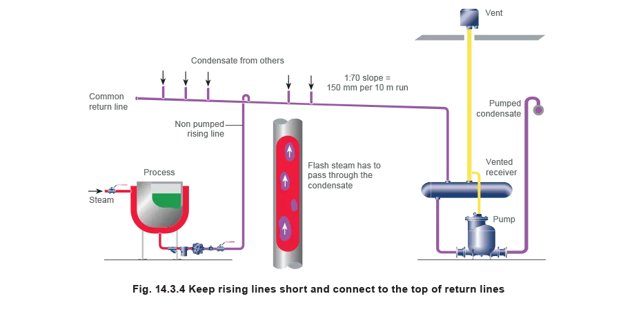
It is sensible to consider using a slightly larger riser, which will produce a lower flash steam velocity.
This will reduce the risk of waterhammer and noise caused by steam trying to force a path through the liquid condensate in the riser.
Important: A rising line should only be used where the process steam pressure is guaranteed to be higher than the condensate backpressure at the trap outlet. If not, the process will waterlog unless a pumping trap or pump-trap combination is used to provide proper drainage against the backpressure.
3. Common return lines should also slope down and be non-flooded (Figure 14.3.4). To avoid flash steam occurring in long return lines, hot condensate from trap discharge lines should drain into vented receivers (or flash vessels where appropriate), from where it can be pumped on to its final destination, via a flooded line at a lower temperature.
Condensate pumping is dealt with in more detail in Module 14.4.
The condensate pipe sizing chart
The condensate pipe sizing chart (Figure 14.3.5) can be used to size any type of condensate line, including:
- Drain lines containing no flash steam.
- Lines consisting of two-phase flow, such as trap discharge lines, which are selected according to the pressures either side of the trap.
The chart (Figure 14.3.5):
- Works around acceptable flash steam velocities of 15 - 20 m/s, according to the pipe size and the proportion of flash steam formed.
- Can be used with condensate temperatures lower than the steam saturation temperature, as will be the case when using thermostatic steam traps.
- Is used to size trap discharge lines on full-load conditions. It is not necessary to consider any oversizing factors for start-up load or the removal of non-condensable gases.
- May also be used to estimate sizes for pumped lines containing condensate below 100°C. This will be discussed in Module 14.4.
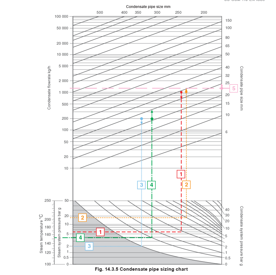
Using the condensate pipe sizing chart (Also available in Appendix 14.3.2)
Establish the point where the steam and condensate pressures meet (lower part of the chart, Figure 14.3.5). From this point, move vertically up to the upper chart to meet the required condensate rate. If the discharge line is falling (non-flooded) and the selection is on or between lines, choose the lower line size. If the discharge line is rising, and therefore likely to be flooded, choose the upper line size.
Note: The reasoning employed for the sizing of a steam trap is different to that used for a discharge line, and it is perfectly normal for a trap discharge line to be sized different to the trap it is serving. However, when the trap is correctly sized, the usual ancillary equipment associated with a steam trap station, such as isolation valves, strainer, trap testing chamber, and check valve, can be the same size as the trapping device selected, whatever the discharge line size.
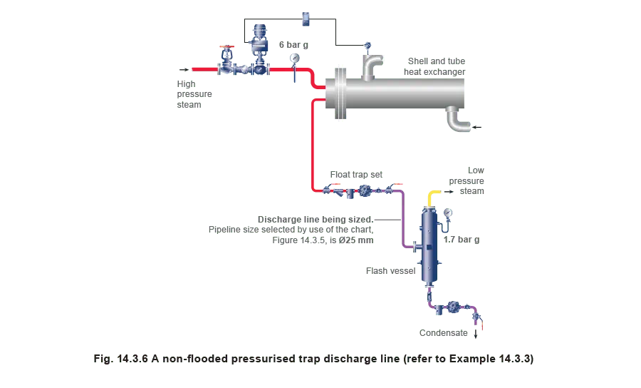
Example 14.3.3 1 On the chart (Figure 14.3.6)
A steam trap passing a full-load of 1000 kg/h at 6 bar g saturated steam pressure through a falling discharge line down to a flash vessel at 1.7 bar g.
As the discharge line is non-flooded, the lower figure of 25 mm is selected from the chart (Figure 14.3.5).
Example 14.3.4 2 on the chart (Figure 14.3.7)
A steam trap passing a full-load of 1 000 kg/h at 18 bar g saturated steam pressure through a discharge line rising 5 m up to a pressurised condensate return line at 3.5 bar g.
Add the 0.5 bar static pressure (5 m head) to the 3.5 bar condensate pressure to give 4 bar g backpressure.
As the discharge line is rising and thus flooded, the upper figure of 32 mm is selected from the chart, (Figure 14.3.5).

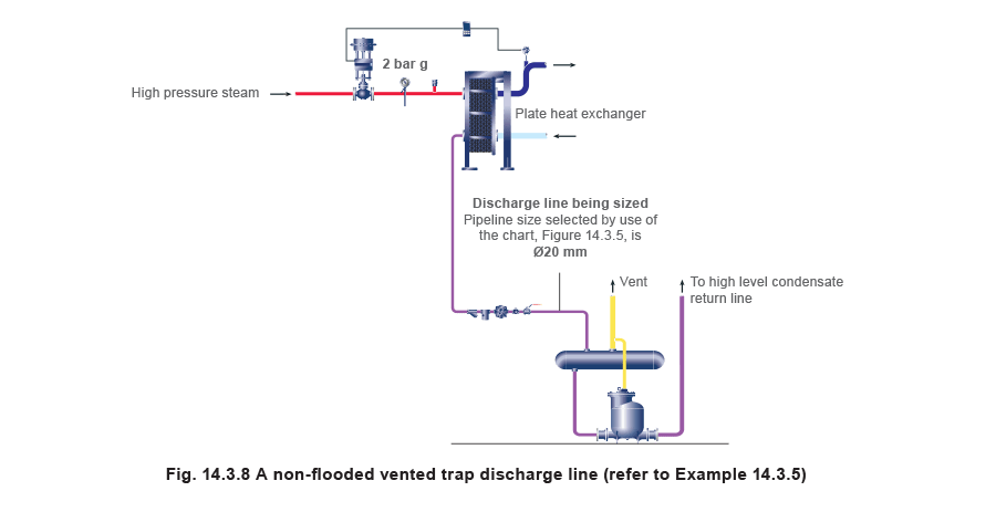
Example 14.3.5 3 on the chart (Figure 14.3.8)
A steam trap passing a full-load of 200 kg/h at 2 bar g saturated steam pressure through a sloping discharge line falling down to a vented condensate receiver at atmospheric pressure (0 bar g).
As the line is non-flooded, the lower figure of 20 mm is selected from the chart, (Figure 14.3.5).
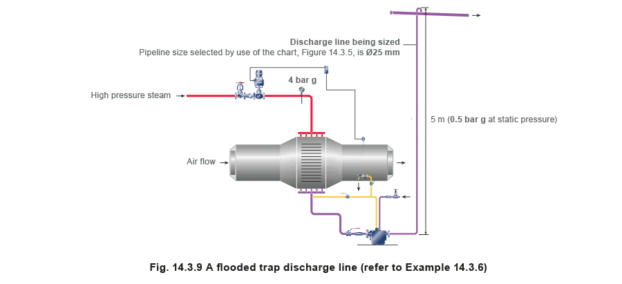
Example 14.3.6 4 on the chart (Figure 14.3.9)
A pump-trap passing a full-load of 200 kg/h at 4 bar g saturated steam space pressure through a discharge line rising 5 m up to a non-flooded condensate return line at atmospheric pressure.
The 5 m static pressure contributes the total backpressure of 0.5 bar g.
As the trap discharge line is rising, the upper figure of 25 mm is selected from the chart, (Figure 14.3.5).
Example 14.3.7 5 on the chart (Figure 14.3.10)
Consider a condensate load of 200 kg/h to a receiver and pump. In this case, the condensate line is based on the maximum capacity of the pump to achieve the desired delivery head. Calculating pump capacities is covered in Module 14.4 ‘Pumping Condensate from Vented Receivers’, but for this example, it is assumed that the maximum condensate load will be 1 200 kg/h.
Because the condensate will have lost its flash steam content to atmosphere via the receiver vent, the pump will only be pumping liquid condensate. In this instance, it is only necessary to use the top part of the chart in Figure 14.3.5. As the line from the pump is rising, the upper figure of 25 mm is chosen.
Note: If the pumped line were longer than 100 m, the next larger size must be taken, which for this example would be 32 mm. A useful tip for lines of 100 m or less is to choose a discharge pipe which is the same size as the pump. For further details refer to Module 14.4 ‘Pumping condensate from vented receivers’.

Common return lines - falling lines
It is sometimes necessary to connect several trap discharge lines from separate processes into a common return line. Problems will not occur if the following considerations are met:
- The common line is not flooded and slopes in the direction of flow to an open end or a vented receiver, or a flash vessel if the conditions allow.
- The common line is sized on the cumulative sizes of the branch lines, and the branch lines are sized from Figure 14.3.5.
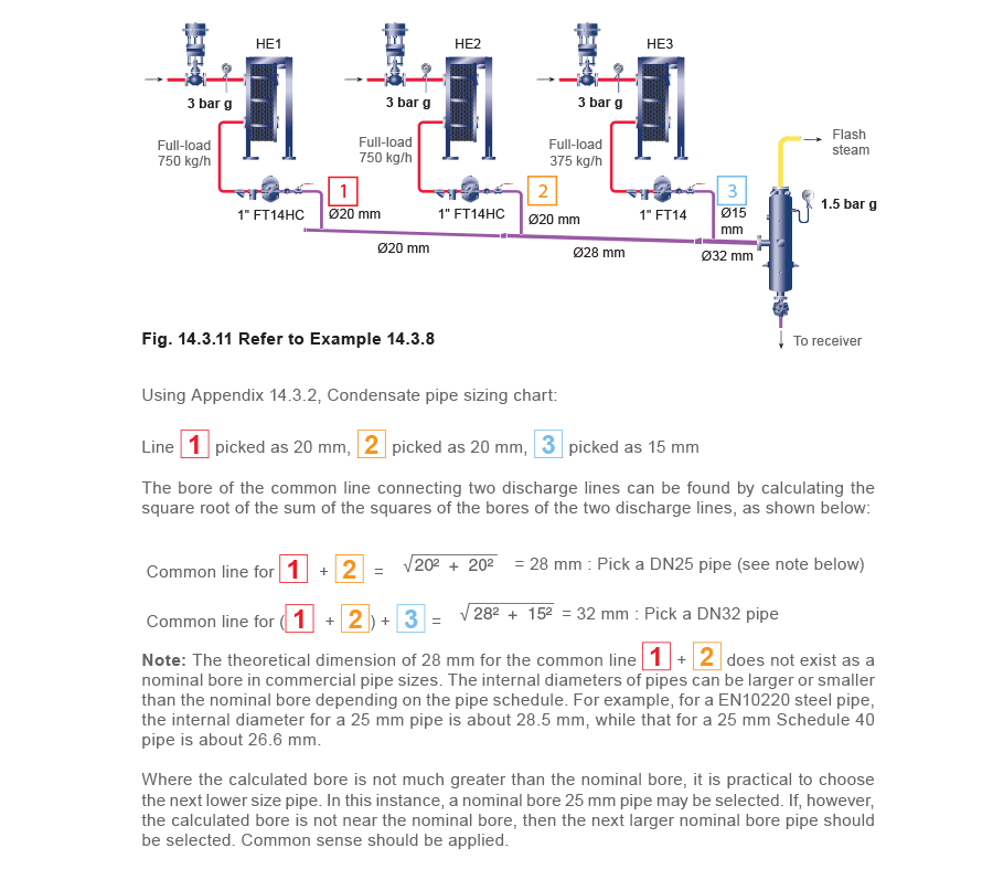
Example 14.3.8
Figure 14.3.11 shows three heat exchangers, each separately controlled and operating at the same time. The condensate loads shown are full loads and occur with 3 bar g in the steam space.
The common line slopes down to the flash vessel at 1.5 bar g, situated in the same plant room. Condensate in the flash vessel falls via a float trap down to a vented receiver, from where it is pumped directly to the boiler house.
The trap discharge lines are sized on full-load with steam pressure at 3 bar g and condensate pressure of 1.5 bar g, and as each is not flooded, the lower line sizes are picked from the graph.
Determine the condensate line sizes for the falling discharge lines and common lines.
Common return lines - rising lines
It is sometimes unavoidable for condensate discharge and common lines to rise at some point between the trap and the point of final termination. When this is the case, each discharge line is sized by moving up to the next size on the chart, as previously discussed in this Module.
Example 14.3.9
Figure 14.3.12 shows the same three heat exchangers as in Example 14.3.8.
However, in this instance, the common line rises 15 m and terminates in an overhead non-flooded condensate return main, giving the same backpressure of 1.5 bar as in Example 14.3.8. Each of the discharge lines is sized as a rising line.
Determine the condensate line sizes for the discharge lines and common lines.

Example 14.3.10 - Falling common line
Calculating the common line sizes for the application shown in Fig. 14.3.12 which falls to a final termination point:

Example 14.3.11 - Rising common line
Calculating the common line sizes for the application shown in Fig. 14.3.14 which rises to a final termination point:
Note that the steam loads are the same as Example 14.3.10, but the discharge lines are one size larger due to the rising common line.
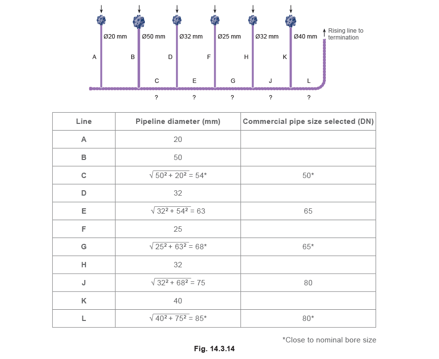
The procedure shown in Examples 14.3.10 and 14.3.11 can be simplified by using Appendix 14.3.3.
For example, where pipes A and B (20 mm and 50 mm) join, the minimum required pipe diameter is shown as 54 mm. Clearly, the user would fit the next largest size of commercial pipe available, unless the calculated bore is close to a nominal bore size pipe.
Appendix 14.3.1 Flow of water in heavy steel pipes
| Flowrate | kg/h | ||||||||||
| Pipe size Ø | 15 mm |
20 mm |
25 mm |
32 mm |
40 mm |
50 mm |
65 mm |
80 mm |
100 mm |
||
| Pa/m | mbar/m | <0.15 m/s | 0.15 m/s | 0.3 m/s | |||||||
| 10 | 0.1 | 50 | 119 | 223 | 490 | 756 | 1 447 | 2 966 | 4 644 | 9 432 | |
| 12.5 | 0.125 | 58 | 133 | 252 | 554 | 853 | 1 634 | 3 348 | 5 220 | 10 656 | |
| 15 | 0.15 | 65 | 151 | 277 | 616 | 943 | 1 807 | 3 708 | 5 760 | 11 736 | |
| 17.5 | 0.175 | 68 | 162 | 302 | 670 | 1 026 | 1 966 | 4 032 | 6 264 | 12 744 | |
| 20 | 0.2 | 76 | 176 | 328 | 720 | 1 105 | 2 113 | 4 320 | 6 732 | 13 680 | |
| 22.5 | 0.225 | 79 | 187 | 349 | 770 | 1 177 | 2 254 | 4 608 | 7 164 | 14 580 | 0.5 m/s |
| 25 | 0.25 | 83 | 198 | 371 | 814 | 1 249 | 2 387 | 4 860 | 7 596 | 15 408 | |
| 27.5 | 0.275 | 90 | 209 | 389 | 857 | 1 314 | 2 513 | 5 112 | 7 992 | 16 200 | |
| 30 | 0.3 | 94 | 220 | 410 | 900 | 1 379 | 2 632 | 5 364 | 8 352 | 16 956 | |
| 32.5 | 0.325 | 97 | 230 | 428 | 940 | 1 440 | 2 747 | 5 616 | 8 712 | 17 712 | |
| 35 | 0.35 | 101 | 241 | 446 | 979 | 1 498 | 2 858 | 5 832 | 9 072 | 18 432 | |
| 37.5 | 0.375 | 104 | 248 | 464 | 1 015 | 1 555 | 2 966 | 6 048 | 9 396 | 19 116 | |
| 40 | 0.4 | 112 | 259 | 479 | 1 051 | 1 609 | 3 071 | 6 264 | 9 720 | 19 764 | |
| 42.5 | 0.425 | 115 | 266 | 497 | 1 087 | 1 663 | 3 175 | 6 480 | 10 044 | 20 412 | |
| 45 | 0.45 | 119 | 277 | 511 | 1 123 | 1 717 | 3 272 | 6 660 | 10 368 | 21 024 | |
| 47.5 | 0.475 | 122 | 284 | 526 | 1 156 | 1 768 | 3 370 | 6 876 | 10 656 | 21 636 | |
| 50 | 0.5 | 126 | 292 | 540 | 1 188 | 1 814 | 3 463 | 7 056 | 10 944 | 22 212 | |
| 52.5 | 0.525 | 130 | 299 | 558 | 1 220 | 1 865 | 3 553 | 7 236 | 11 232 | 22 788 | |
| 55 | 0.55 | 130 | 306 | 572 | 1 249 | 1 912 | 3 636 | 7 416 | 11 520 | 23 364 | |
| 57.5 | 0.575 | 133 | 317 | 583 | 1 282 | 1 958 | 3 744 | 7 596 | 11 808 | 23 904 | |
| 60 | 0.6 | 137 | 324 | 598 | 1 310 | 2 002 | 3 816 | 7 776 | 12 060 | 24 444 | |
| 62.5 | 0.625 | 140 | 331 | 612 | 1 339 | 2 048 | 3 888 | 7 920 | 12 312 | 24 984 | |
| 65 | 0.65 | 144 | 338 | 626 | 1 368 | 2 092 | 3 996 | 8 100 | 12 600 | 25 488 | |
| 67.5 | 0.675 | 148 | 346 | 637 | 1 397 | 2 131 | 4 068 | 8 280 | 12 852 | 25 992 | |
| 70 | 0.7 | 151 | 353 | 652 | 1 422 | 2 174 | 4 140 | 8 424 | 13 068 | 26 496 | |
| 72.5 | 0.725 | 151 | 356 | 662 | 1 451 | 2 218 | 4 212 | 8 568 | 13 320 | 27 000 | |
| 75 | 0.75 | 155 | 364 | 677 | 1 476 | 2 257 | 4 284 | 8 748 | 13 572 | 27 468 | |
| 77.5 | 0.775 | 158 | 371 | 688 | 1 505 | 2 297 | 4 356 | 8 892 | 13 788 | 27 972 | |
| 80 | 0.8 | 162 | 378 | 698 | 1 530 | 2 336 | 4 464 | 9 036 | 14 040 | 28 440 | 1 m/s |
| 82.5 | 0.825 | 166 | 385 | 709 | 1 555 | 2 372 | 4 536 | 9 180 | 14 256 | 28 872 | |
| 85 | 0.85 | 166 | 389 | 724 | 1 580 | 2 412 | 4 608 | 9 324 | 14 472 | 29 340 | |
| 87.5 | 0.875 | 169 | 396 | 734 | 1 606 | 2 448 | 4 680 | 9 468 | 14 724 | 29 772 | |
| 90 | 0.9 | 173 | 403 | 745 | 1 627 | 2 488 | 4 716 | 9 612 | 14 940 | 30 240 | |
| 92.5 | 0.925 | 176 | 407 | 756 | 1 652 | 2 524 | 4 788 | 9 756 | 15 156 | 30 672 | |
| 95 | 0.95 | 176 | 414 | 767 | 1 678 | 2 560 | 4 860 | 9 900 | 15 372 | 31 104 | |
| 97.5 | 0.975 | 180 | 421 | 778 | 1 699 | 2 596 | 4 932 | 10 044 | 15 552 | 31 500 | |
| 100 | 1 | 184 | 425 | 788 | 1 724 | 2 632 | 5 004 | 10 152 | 15 768 | 31 932 | |
| 120 | 1.2 | 202 | 472 | 871 | 1 897 | 2 898 | 5 508 | 11 196 | 17 352 | 35 100 | |
| 140 | 1.4 | 220 | 511 | 943 | 2 059 | 3 143 | 5 976 | 12 132 | 18 792 | 38 160 | |
| 160 | 1.6 | 234 | 547 | 1 015 | 2 210 | 3 373 | 6 408 | 12 996 | 20 160 | 40 680 | |
| 180 | 1.8 | 252 | 583 | 1 080 | 2 354 | 3 589 | 6 804 | 13 824 | 21 420 | 43 200 | 1.5 m/s |
| 200 | 2 | 266 | 619 | 1 141 | 2 488 | 3 780 | 7 200 | 14 580 | 22 644 | 45 720 | |
| 220 | 2.2 | 281 | 652 | 1 202 | 2 617 | 3 996 | 7 560 | 15 336 | 23 760 | 47 880 | |
| 240 | 2.4 | 288 | 680 | 1 256 | 2 740 | 4 176 | 7 920 | 16 056 | 24 876 | 50 400 | |
| 260 | 2.6 | 306 | 713 | 1 310 | 2 855 | 4 356 | 8 244 | 16 740 | 25 920 | 52 200 | |
| 280 | 2.8 | 317 | 742 | 1 364 | 2 970 | 4 536 | 8 568 | 17 388 | 26 928 | 54 360 | |
| 300 | 3 | 331 | 767 | 1 415 | 3 078 | 4 680 | 8 892 | 18 000 | 27 900 | 56 160 | |

Appendix 14.3.3 Common pipe sizing table
D1 = Connecting branch size (N.B.) D2 = Common pipe size
| D2 | D1 - Connecting branch size (NB) | ||||||||
| 15 | 20 | 25 | 32 | 40 | 50 | 65 | 80 | 100 | |
| 15 | 21 | 25 | 29 | 35 | 43 | 52 | 67 | 81 | 101 |
| 16 | 22 | 26 | 30 | 36 | 43 | 52 | 67 | 82 | 101 |
| 17 | 23 | 26 | 30 | 36 | 43 | 53 | 67 | 82 | 101 |
| 18 | 23 | 27 | 31 | 37 | 44 | 53 | 67 | 82 | 102 |
| 19 | 24 | 28 | 31 | 37 | 44 | 53 | 68 | 82 | 102 |
| 20 | 25 | 28 | 32 | 38 | 45 | 54 | 68 | 82 | 102 |
| 21 | 26 | 29 | 33 | 38 | 45 | 54 | 68 | 83 | 102 |
| 22 | 27 | 30 | 33 | 39 | 46 | 55 | 69 | 83 | 102 |
| 23 | 27 | 30 | 34 | 39 | 46 | 55 | 69 | 83 | 103 |
| 24 | 28 | 31 | 35 | 40 | 47 | 55 | 69 | 84 | 103 |
| 25 | 29 | 32 | 35 | 41 | 47 | 56 | 70 | 84 | 103 |
| 26 | 30 | 33 | 36 | 41 | 48 | 56 | 70 | 84 | 103 |
| 27 | 31 | 34 | 37 | 42 | 48 | 57 | 70 | 84 | 104 |
| 28 | 32 | 34 | 38 | 43 | 49 | 57 | 71 | 85 | 104 |
| 29 | 33 | 35 | 38 | 43 | 49 | 58 | 71 | 85 | 104 |
| 30 | 34 | 36 | 39 | 44 | 50 | 58 | 72 | 85 | 104 |
| 31 | 34 | 37 | 40 | 45 | 51 | 59 | 72 | 86 | 105 |
| 32 | 35 | 38 | 41 | 45 | 51 | 59 | 72 | 86 | 105 |
| 33 | 36 | 39 | 41 | 46 | 52 | 60 | 73 | 87 | 105 |
| 34 | 37 | 39 | 42 | 47 | 52 | 60 | 73 | 87 | 106 |
| 35 | 38 | 40 | 43 | 47 | 53 | 61 | 74 | 87 | 106 |
| 36 | 39 | 41 | 44 | 48 | 54 | 62 | 74 | 88 | 106 |
| 37 | 40 | 42 | 45 | 49 | 54 | 62 | 75 | 88 | 107 |
| 38 | 41 | 43 | 45 | 50 | 55 | 63 | 75 | 89 | 107 |
| 39 | 42 | 44 | 46 | 50 | 56 | 63 | 76 | 89 | 107 |
| 40 | 43 | 45 | 47 | 51 | 57 | 64 | 76 | 89 | 108 |
| 41 | 44 | 46 | 48 | 52 | 57 | 65 | 77 | 90 | 108 |
| 42 | 45 | 47 | 49 | 53 | 58 | 65 | 77 | 90 | 108 |
| 43 | 46 | 47 | 50 | 54 | 59 | 66 | 78 | 91 | 109 |
| 44 | 46 | 48 | 51 | 54 | 59 | 67 | 78 | 91 | 109 |
| 45 | 47 | 49 | 51 | 55 | 60 | 67 | 79 | 92 | 110 |
| 46 | 48 | 50 | 52 | 56 | 61 | 68 | 80 | 92 | 110 |
| 47 | 49 | 51 | 53 | 57 | 62 | 69 | 80 | 93 | 110 |
| 48 | 50 | 52 | 54 | 58 | 62 | 69 | 81 | 93 | 111 |
| 49 | 51 | 53 | 55 | 59 | 63 | 70 | 81 | 94 | 111 |
| 50 | 52 | 54 | 56 | 59 | 64 | 71 | 82 | 94 | 112 |
| 51 | 53 | 55 | 57 | 60 | 65 | 71 | 83 | 95 | 112 |
| 52 | 54 | 56 | 58 | 61 | 66 | 72 | 83 | 95 | 113 |
| 53 | 55 | 57 | 59 | 62 | 66 | 73 | 84 | 96 | 113 |
| 54 | 56 | 58 | 60 | 63 | 67 | 74 | 85 | 97 | 114 |
| 55 | 57 | 59 | 60 | 64 | 68 | 74 | 85 | 97 | 114 |
| 56 | 58 | 59 | 61 | 64 | 69 | 75 | 86 | 98 | 115 |
| 57 | 59 | 60 | 62 | 65 | 70 | 76 | 86 | 98 | 115 |
| D2 | D1 - Connecting branch size (NB) | ||||||||
| 15 | 20 | 25 | 32 | 40 | 50 | 65 | 80 | 100 | |
| 58 | 60 | 61 | 63 | 66 | 70 | 77 | 87 | 99 | 116 |
| 59 | 61 | 62 | 64 | 67 | 71 | 77 | 88 | 99 | 116 |
| 60 | 62 | 63 | 65 | 68 | 72 | 78 | 88 | 100 | 117 |
| 61 | 63 | 64 | 66 | 69 | 73 | 79 | 89 | 101 | 117 |
| 62 | 64 | 65 | 67 | 70 | 74 | 80 | 90 | 101 | 118 |
| 63 | 65 | 66 | 68 | 71 | 75 | 80 | 91 | 102 | 118 |
| 64 | 66 | 67 | 69 | 72 | 75 | 81 | 91 | 102 | 119 |
| 65 | 67 | 68 | 70 | 72 | 76 | 82 | 92 | 103 | 119 |
| 66 | 68 | 69 | 71 | 73 | 77 | 83 | 93 | 104 | 120 |
| 67 | 69 | 70 | 72 | 74 | 78 | 84 | 93 | 104 | 120 |
| 68 | 70 | 71 | 72 | 75 | 79 | 84 | 94 | 105 | 121 |
| 69 | 71 | 72 | 73 | 76 | 80 | 85 | 95 | 106 | 121 |
| 70 | 72 | 73 | 74 | 77 | 81 | 86 | 96 | 106 | 122 |
| 71 | 73 | 74 | 75 | 78 | 81 | 87 | 96 | 107 | 123 |
| 72 | 74 | 75 | 76 | 79 | 82 | 88 | 97 | 108 | 123 |
| 73 | 75 | 76 | 77 | 80 | 83 | 88 | 98 | 108 | 124 |
| 74 | 76 | 77 | 78 | 81 | 84 | 89 | 98 | 109 | 124 |
| 75 | 76 | 78 | 79 | 82 | 85 | 90 | 99 | 110 | 125 |
| 76 | 77 | 79 | 80 | 82 | 86 | 91 | 100 | 110 | 126 |
| 77 | 78 | 80 | 81 | 83 | 87 | 92 | 101 | 111 | 126 |
| 78 | 79 | 81 | 82 | 84 | 88 | 93 | 102 | 112 | 127 |
| 79 | 80 | 81 | 83 | 85 | 89 | 93 | 102 | 112 | 127 |
| 80 | 81 | 82 | 84 | 86 | 89 | 94 | 103 | 113 | 128 |
| 81 | 82 | 83 | 85 | 87 | 90 | 95 | 104 | 114 | 129 |
| 82 | 83 | 84 | 86 | 88 | 91 | 96 | 105 | 115 | 129 |
| 83 | 84 | 85 | 87 | 89 | 92 | 97 | 105 | 115 | 130 |
| 84 | 85 | 86 | 88 | 90 | 93 | 98 | 106 | 116 | 131 |
| 85 | 86 | 87 | 89 | 91 | 94 | 99 | 107 | 117 | 131 |
| 86 | 87 | 88 | 90 | 92 | 95 | 99 | 108 | 117 | 132 |
| 87 | 88 | 89 | 91 | 93 | 96 | 100 | 109 | 118 | 133 |
| 88 | 89 | 90 | 91 | 94 | 97 | 101 | 109 | 119 | 133 |
| 89 | 90 | 91 | 92 | 95 | 98 | 102 | 110 | 120 | 134 |
| 90 | 91 | 92 | 93 | 96 | 98 | 103 | 111 | 120 | 135 |
| 91 | 92 | 93 | 94 | 96 | 99 | 104 | 112 | 121 | 135 |
| 92 | 93 | 94 | 95 | 97 | 100 | 105 | 113 | 122 | 136 |
| 93 | 94 | 95 | 96 | 98 | 101 | 106 | 113 | 123 | 137 |
| 94 | 95 | 96 | 97 | 99 | 102 | 106 | 114 | 123 | 137 |
| 95 | 96 | 97 | 98 | 100 | 103 | 107 | 115 | 124 | 138 |
| 96 | 97 | 98 | 99 | 101 | 104 | 108 | 116 | 125 | 139 |
| 97 | 98 | 99 | 100 | 102 | 105 | 109 | 117 | 126 | 139 |
| 98 | 99 | 100 | 101 | 103 | 106 | 110 | 118 | 127 | 140 |
| 99 | 100 | 101 | 102 | 104 | 107 | 111 | 118 | 127 | 141 |
| 100 | 101 | 102 | 103 | 105 | 108 | 112 | 119 | 128 | 141 |