Condensate Removal

Contents
Example Selecting The Trap
A fully worked-through example for calculating stall and selecting a condensate removal solution for a heat exchange application.
Example 13.4.1 Selecting the trap
A factory requires a steam/water heat exchanger operating at a nominal 4 bar g to heat process water circulating at 1 L/s (1 kg/s) from 10°C to 80°C, giving a design load of 293 kW. The process is such that a minimum heat load occurs at 60% of the full heat load. This is a permanently running process line with no future load increase. Two suppliers are asked to provide a heat exchanger. The following information is important to selection:
- Supplier ‘X’ can provide a heat exchanger with a heating area of 2 m2, a ‘U’ value of 2 500 W/m2 °C and duty of 350 kW when operating with steam at 4 bar g and with a water flow of 1 L/s.
- Supplier ‘Y’ is able to provide a heat exchanger with a smaller heating area more suitable for the design heat load of 293 kW, when operating with steam at 4 bar g and with a water flow of 1 L/s.
The ‘U’ value is 2500 W/m2 °C. - The heat exchanger condensate line will lift 5 metres to a condensate return pipe that falls en route to a vented receiver, and having a total backpressure of 0.5 bar g. Note: A one metre column
of water under atmospheric pressure will exert a pressure at the bottom of the column of approximately 10 kPa or 0.1 bar g. Any lift in the condensate discharge line will thus exert a static lift due to the column of condensate held in the line, in addition to any pressure in the condensate system.
It is necessary to determine the system operating conditions to select and size the trap for proper condensate removal from both heat exchangers under any operating load condition.
The following questions need to be answered for proper condensate removal:
(A) Will stall occur during normal operation?
(B) At what load will stall occur?
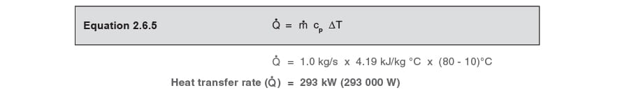
Check the application heat load at the design condition.
From the heat transfer flowrate equation (Equation 2.6.5):
Consider supplier ‘X’
A 350 kW heat exchanger with a 2 m2 heating area.
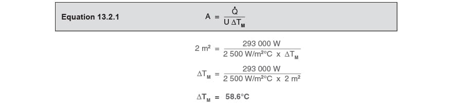
What will be the steam space pressure in this heater at this design heat load?
It is first necessary to determine the LMTD (ΔTLM) for a 2 m2 heating area.
From Equation 13.2.1:
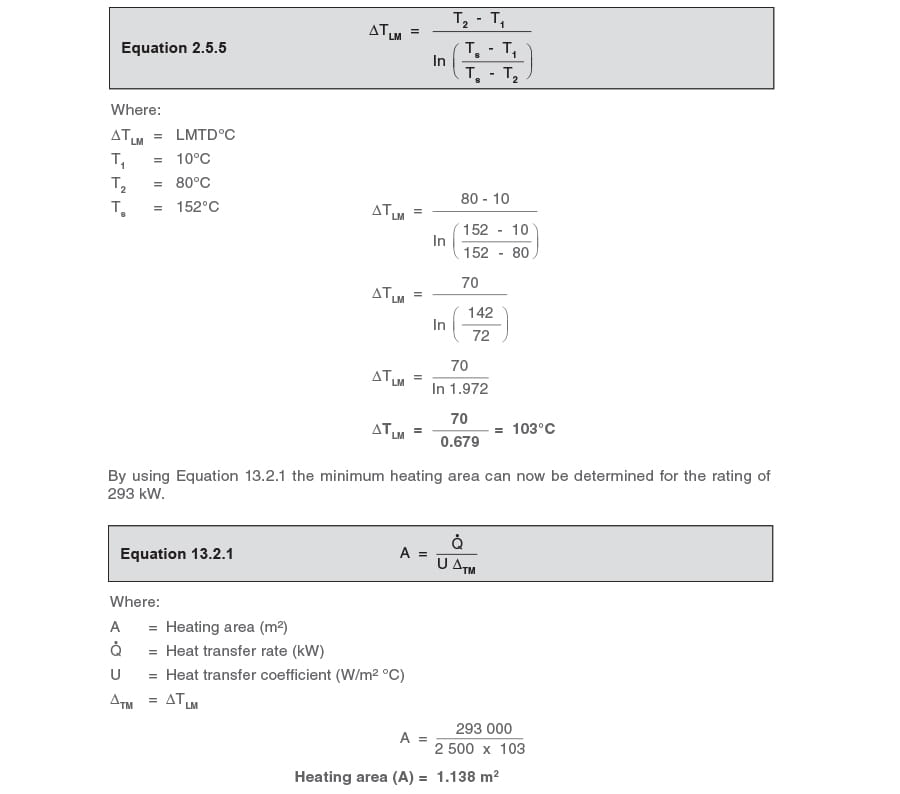
The steam design temperature can now be calculated, by use of Equation 2.5.5:

This saturation temperature is equivalent to a steam pressure of 0.45 bar g. This pressure is less than the 0.5 bar g backpressure, and the system will permanently stall.
In this case, if a ball float steam trap were fitted, condensate would permanently flood the heat exchanger, its level modulating relative to changes in load. Operating performance might be unsatisfactory as the secondary outlet temperature will tend to fluctuate, and the heat exchanger might fail prematurely due to corrosion.
If the system is permanently running under stall conditions, a ball float steam trap is the wrong choice for this application, and a pump-trap should be fitted instead.
Consider supplier ‘Y’
For the manufacturer to size the heating area that best matches the design condition, it is necessary to find the minimum heating area that will satisfy the operating full-load. It is first necessary to determine the rated LMTD for the heat exchanger with a steam space pressure of 4 bar g (TS = 152°C).
From Equation 2.5.5:
From his standard range, supplier ‘Y’ can provide a plate heat exchanger that meets the specification with a heating area of 1.198 m2. This is oversized (by about 5%) and steam pressure will therefore be less than 4 bar g at the full-load operating condition.
In practice, heat exchangers are likely to be specified at least 10% over capacity. It is for this reason that the operating steam pressure (not the quoted normal working pressure) should always be established before selecting and sizing the steam trapping device. The reputable manufacturer should be willing to supply this information, or, at least, the heating area, the ‘U’ value, and the heat output. From this data, the rated LMTD can be calculated, from which the operating pressure can be found.
Find the LMTD for the heat exchanger with a heating area of 1.198 m²:
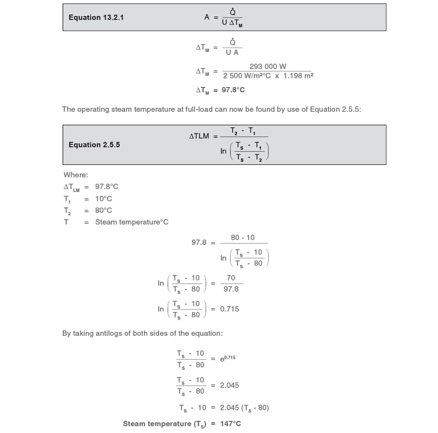
This saturation temperature is equivalent to a steam pressure of 3.4 bar g at the design condition. As this pressure is more than the constant 0.5 bar g backpressure, the system will not stall at full-load.
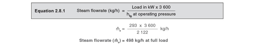
What is the steam flowrate (ṁs) at full-load?
The steam mass flowrate will depend upon the steam space pressure, which is 3.4 bar g at full-load, with an enthalpy of evaporation of 2122 kJ/kg.
From Equation. 2.8.1:
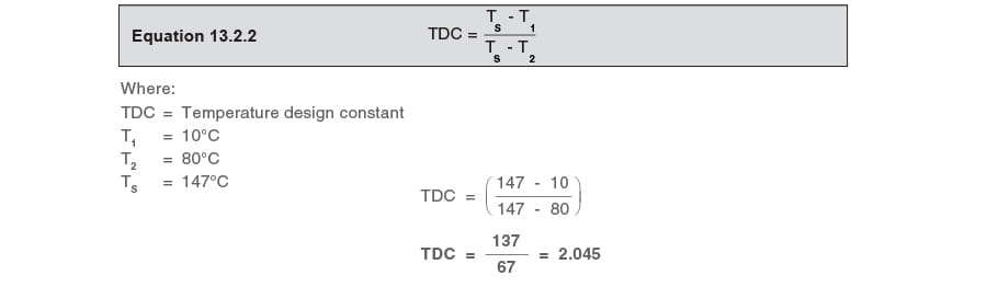
What is the TDC?
It is now necessary to find the heat load at which the system will stall. In order to do so, it is necessary to calculate the TDC for this heat exchanger from the design conditions.
From Equation 13.2.2:
The stall condition
At stall, the pressure in the steam space will equal the 0.5 bar g backpressure.
The saturation temperature of steam at 0.5 bar g is 111.6°C.
From Equation 13.2.4 the inlet temperature can be found:
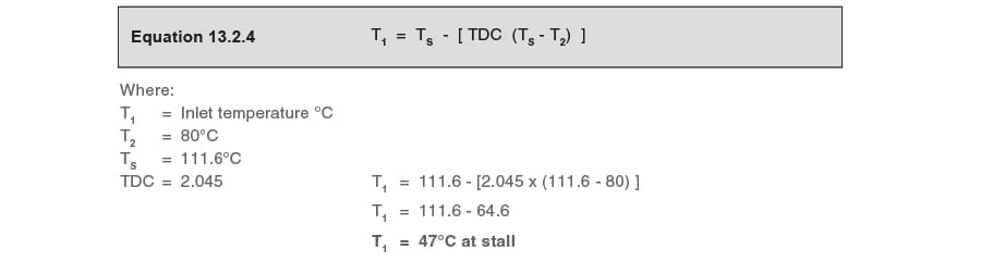
What is the heat load at stall?
From the heat transfer flowrate equation (Equation 2.6.5):
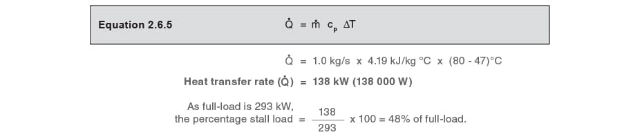
The selection of the trapping device will depend on whether the minimum heat load is higher or lower than the stall load.
The minimum load is quoted as being 60% of the full-load of 293 kW, therefore:
Minimum load = 0.6 x 293 kW = 176 kW
Stall load = 138 kW
As the minimum load is greater than the stall load, the system will never stall. It is therefore practical to fit a ball float steam trap, as there will always be a positive differential pressure across it.
However, the ball float steam trap has to be sized to carry both the full-load and the minimum load, and it is therefore necessary to calculate the steam flows and the corresponding steam space pressures at both conditions.
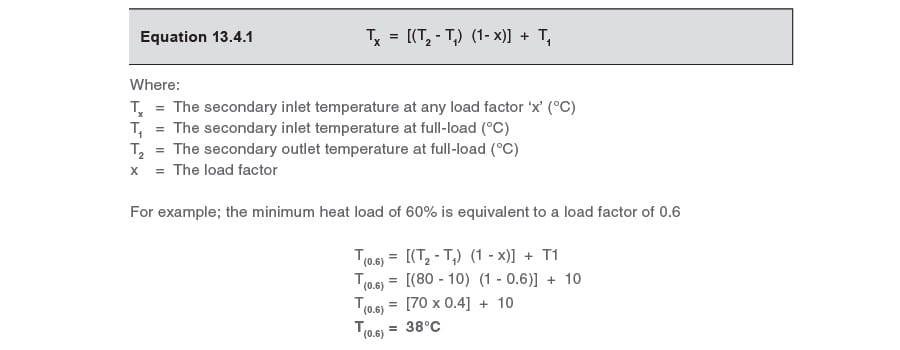
It is first necessary to calculate the secondary inlet temperature at the minimum load. This can be predicted by use of Equation 13.4.1:
The minimum load condition
From Equation 13.2.3:
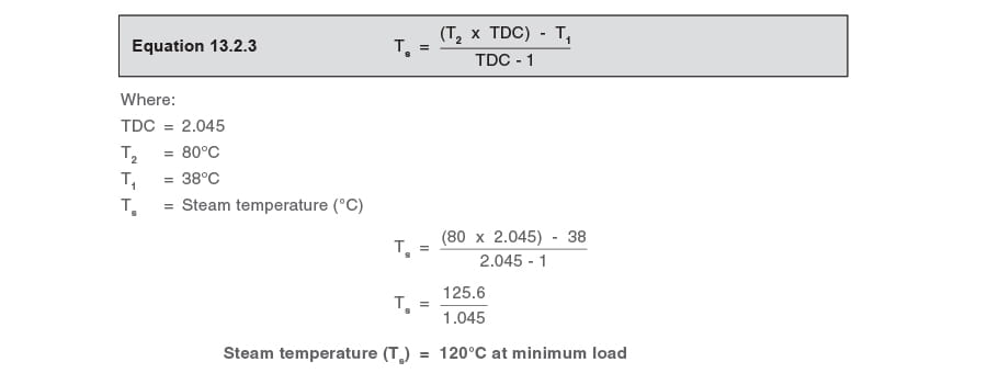
This is the steam temperature at the minimum load of 176 kW, and is equivalent to a steam pressure of 1.0 bar g. The condensate pressure is 0.5 bar g. The differential pressure across the ball float steam trap at minimum load therefore equals 1.0 bar g - 0.5 bar g = 0.5 bar.
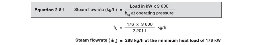
What is the steam flowrate (ṁ (min)) at the minimum heat load of 176 kW?
The minimum steam flowrate will depend upon the steam space pressure, which is 1.0 bar g with an enthalpy of evaporation of 2201.1 kJ/kg.
From Equation 2.8.1:
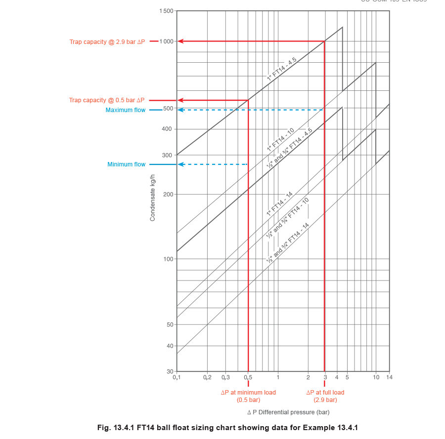
As it has been established that this system will not stall, a ball float steam trap is suitable. It is now necessary to size a ball float steam trap for operation up to the maximum system differential pressure of 3.5 bar and pass . . .
a) the full-load of 498 kg/h with a differential pressure of 3.4 bar g - 0.5 bar g = 2.9 bar g.
b) the minimum load of 288 kg/h with a differential pressure of 1.0 bar g - 0.5 bar g = 0.5 bar g.
It can be seen from the ball float steam trap sizing chart (Figure 13.4.1) that a DN25 (1”) FT14-4.5 will satisfy both of these conditions, and could be selected. However, if the minimum heat load were less than the stall load, then a pump-trap would have to be selected.
The methods of selecting trapping devices are further discussed in Module 13.8, ‘Practical methods of preventing stall’.