Condensate Removal

Contents
Oversized Heat Exchangers
Heat exchangers are often bought oversized for the required duty. This tutorial looks at the reasons why, the effects this has and related requirements, such as trap sizing for oversized exchangers.
The previous calculations (Module13.2) assumed that the heat exchanger had been sized on the perfect heating area to meet the specification. This would mean that the heat exchanger was exactly sized for the duty.
This is highly unlikely in practice as the designer or specifier will usually add other factors, including those for fouling and uncertainty of maximum operating loads. It is also unlikely that manufacturers can supply heat exchangers to match a specification exactly. As undersized heat exchangers are impractical they are usually bought oversized.
The operating conditions laid down in Example 13.2.1, Part ‘C’, have been reconsidered in Example 13.3.1 by adding 15% to the required heating area to account for contingencies.
Required heating area is calculated to be 1.09 m² (Example 13.2.1, Part ‘C’) therefore the specified heating area for Example 13.3.1 is to be 1.09 + 15% = 1.254 m².
The minimum size that the manufacturer can supply has a heating area of 1.31 m², representing an actual heating area of some 20% above that required. A larger heating area requires less steam pressure for the same heat transfer rate, and because of this the steam pressure in an oversized heat exchanger will be lower for the same heat load.
As the steam pressure is less, the steam temperature is less, and the heat exchanger LMTD (Logarithmic Mean Temperature Difference) will also be less.
To determine the steam temperature for the design condition, it is first necessary to find the new LMTD (ΔTLM) for the larger heating area (see Example 13.3.1).
Example 13.3.1
The ΔTLM can be found by re-arranging Equation 13.2.1 to give Equation 13.3.1
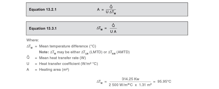
From Example 13.2.2, at full-load:
The secondary inlet temperature (T1) = 10°C
The secondary outlet temperature (T2) = 60°C
The new steam design temperature can now be determined using Equation 2.5.5:
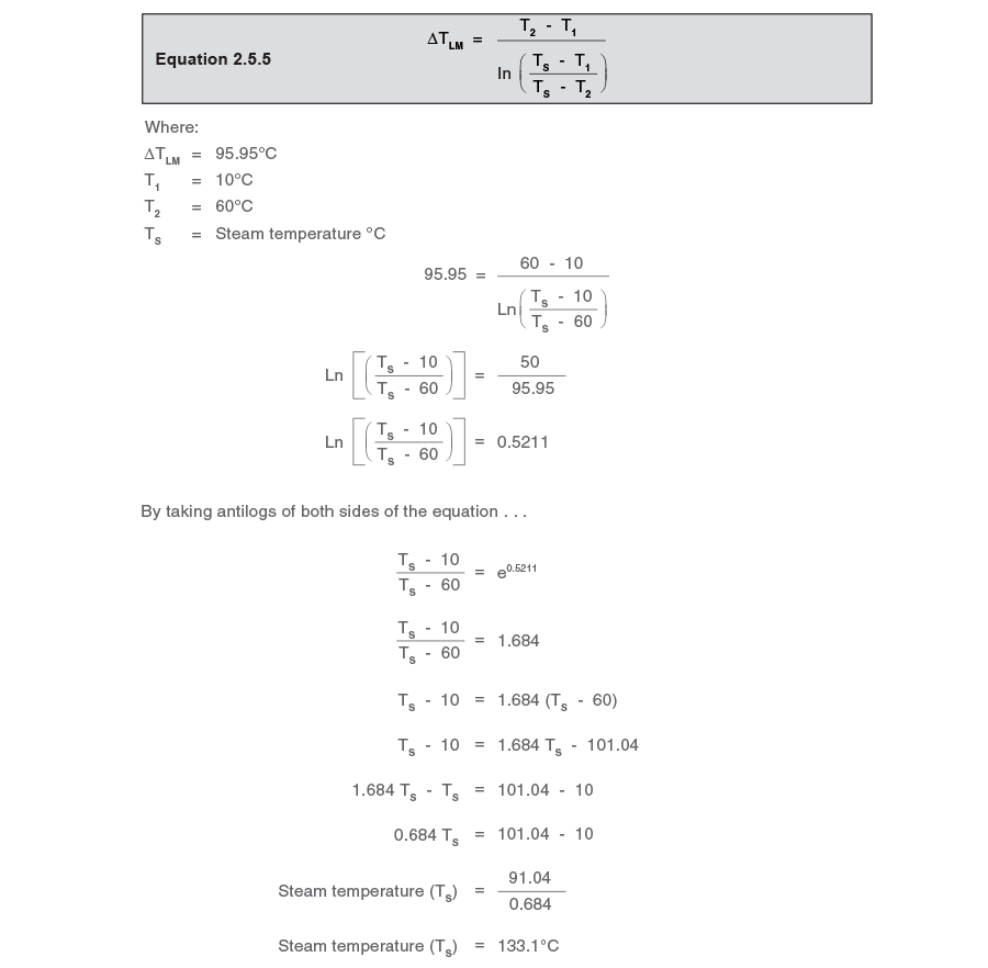
This temperature corresponds to a steam pressure of 1.95 bar g. When the heat exchanger was perfectly sized in Module 13.2, the steam pressure was 4 bar g. In this example, with a heat exchanger 20% oversized, the steam pressure is 51% less.
Now that the steam pressure has been predicted at the full-load condition, it is possible to calculate the steam flow at full-load.
By using Equation 2.8.1 find the steam flowrate at the full heat load of 314.25 kW. At 1.95 bar g, steam tables state that the enthalpy of evaporation is 2 164.6 kJ/kg.
The steam flow was 536.6 kg/h in the perfectly sized heat exchanger (Example 13.2.1), so it can be seen that there is a slight drop (2.5%) in mass flowrate. This is due to the steam having a slightly larger enthalpy of evaporation in the larger heat exchanger due to its lower pressure.
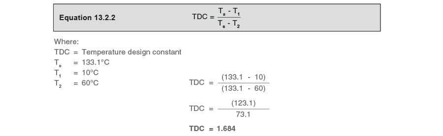
Determine the TDC for the larger heat exchanger
Now that the steam temperature has been determined for the oversized heat exchanger (using the LMTD equation [Equation 2.5.5]), it is now possible to find its TDC, using Equation 13.2.2.
At the minimum heat load:
When the heat exchanger was perfectly sized in Example 13.2.1 the steam temperature was 115.2°C at the minimum heat load of 188.5 kW.
Because the oversized heat exchanger in this example is about 20% larger, the steam temperature will also be less at the minimum heat load. The minimum heat load remains the same as in Example 13.2.1 and occurs when the secondary inlet temperature rises to 30°C.
From Equation 13.2.3:
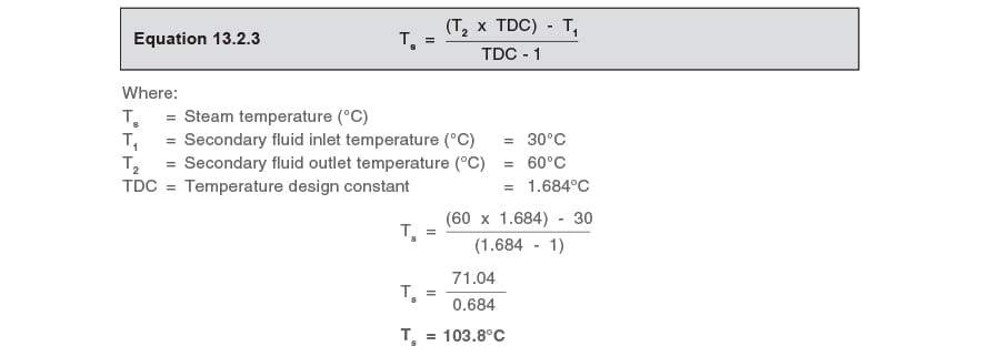
Comparing the two heat exchangers at minimum load, the steam temperature has dropped from 115.2°C in the perfectly sized heat exchanger to 103.8°C in the oversized heat exchanger.
From steam tables, this steam temperature corresponds with a steam pressure of about 0.15 bar g, and hfg = 2 247 kJ/kg. The steam pressure in the perfectly sized exchanger (at 115.2°C) was 0.7 bar g.
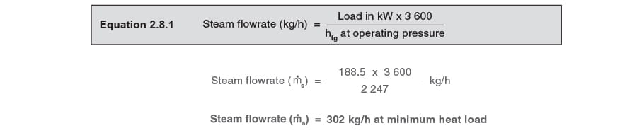
By using Equation 2.8.1, it is possible to find the steam flow at the minimum heat load of 188.5 kW.
The minimum steam flow was 306 kg/h in the perfectly sized heat exchanger (Example 3.2.1), so it can be seen that there is a marginal drop in mass flow in the oversized heat exchanger at the minimum heat load. This is due to the steam having a slightly larger enthalpy of evaporation in the larger heat exchanger due to its lower pressure.
The steam pressure, the steam trap, and effective condensate removal
As the steam gives up its heat across the heat transfer surface to the secondary fluid, it condenses in the steam space. Condensate passes out through the outlet of the heat exchanger, and through a steam trap, which traps the steam in the steam space whilst allowing the condensate to be freely discharged.
If the heat exchanger has not been specifically designed to operate with condensate flooding the steam space, the steam pressure needs careful consideration to ensure the heat exchanger is properly drained of condensate. Any waterlogging of the steam space will reduce the effective heating surface area, and the heat transfer requirement may be satisfied only if the exchanger is sufficiently (perhaps accidentally) oversized.
The capacity of the steam trap will depend upon its type, its orifice size and the differential pressure across it. Differential pressure provides the energy to push the condensate through the trap, and is the difference between the steam pressure in the heat exchanger, and the backpressure exerted on the outlet of the trap by the condensate system.
If the steam trap drains by gravity via a properly sized pipe to a vented condensate receiver or an open end, the backpressure should be very near atmospheric. Under these conditions, the differential pressure on a sizing chart can simply be read as the gauge pressure in the heat exchanger.
If, however, there is a lift after the trap (a rise in the trap discharge line), or the trap discharge line is undersized, or this line is pressurised for any other reason, the backpressure may, at times, be greater than the pressure in the steam space. When this is so, the differential pressure across the trap is reversed and is deemed to be a ‘negative differential pressure’. The trap capacity is now zero.
As can be seen in the above calculations, the steam pressure in any heat exchanger is governed by its size and the secondary conditions. As the capacity of the steam trap depends on the differential pressure, it follows that changes in the steam pressure and backpressure affect the capacity of the steam trap at all times. As the differential pressure reduces, the capacity of the steam trap will fall. Provided the differential pressure is positive and the steam trap is selected and sized with this in mind, waterlogging and its associated problems will not occur.
Sizing the steam trap for the oversized heat exchanger
The conditions that need consideration are:
- Full-load : 523 kg/h at 1.95 bar g in the steam space
- Minimum load : 302 kg/h at 0.15 bar g in the steam space
- Backpressure : Atmospheric pressure (0 bar g)
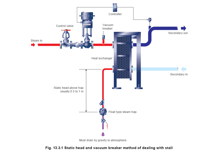
Consider, on the float trap capacity chart Figure 13.3.2, a DN25 (1”) FT14-4.5 ball float steam trap. It can be seen that it will pass 850 kg / h at a differential pressure of 1.95 bar. It may also be seen that at a differential pressure of 0.15 bar it will pass about 370 kg/h. In this example, consider the trap fitted to the oversized heat exchanger and draining by gravity to a vented condensate receiver, as depicted in Figure 13.3.1.
To ensure proper drainage, the steam trap has to be able to cope with all loads between the full-load and minimum load conditions.
As the condensate backpressure is atmospheric in this example, the minimum steam space pressure of 0.15 bar g is always higher than the backpressure. It can be seen from the capacity chart (Figure 13.3.2) that the trap has enough capacity at the minimum and maximum loads, so the DN25 (1") FT14-4.5 ball float steam trap is big enough.
If, however, in this example, the backpressure were higher than the minimum steam pressure of 0.15 bar g, the system would stall somewhere within the normal operating range. (This would only require a lift of just more than 1.5 metres after the trap to cause this). Accordingly, the trap would have to be selected and sized depending upon the amount of backpressure. With larger amounts of backpressure it may be necessary to fit a pump-trap.
Advice on how to select the correct trap for a heat exchanger is given in Module 13.4.
