Condensate Removal

Contents
The Heat Load, Heat Exchanger and Steam Load Relationship
Calculations for heat exchange applications including the design loads and the steam pressure/flowrate requirements
Saturated steam is used to provide primary heat to a process fluid in a heat exchanger. The term heat exchanger is used to describe all types of equipment where heat transfer is promoted from one fluid to another. For convenience, this broad definition will be applied to the term heat exchanger. While shell and tube heat exchangers and plate heat exchangers will be principally referred to, stall may also be relevant to applications including air heater batteries, submerged tank coils, jacketed vessels and storage calorifiers.
Temperature controlled applications
In a temperature control application, the inlet temperature of the secondary fluid to the heat exchanger may change with time. This means that in order to maintain a consistent secondary fluid outlet temperature, the heat supplied to the heat exchanger must also vary. This can be achieved by using a control valve on the inlet to the primary side of the heat exchanger, as shown in Figure 13.2.1..

A control valve is used to vary the flowrate and pressure of the steam so that the heat input to the heat exchanger can be controlled. Modulating the position of the control valve then controls the outlet temperature of the secondary fluid. A sensor on the secondary fluid outlet monitors its temperature, and provides a signal for the controller. The controller compares the actual temperature with the set temperature and, as a result, signals the actuator to adjust the position of the control valve.
For a constant heating area and heat transfer coefficient, the rate at which heat is transferred from the steam to the secondary fluid for a particular heat exchanger is determined by the mean temperature difference between the two fluids. A larger difference in mean temperatures will create a large heat transfer rate and vice versa. On partially closing the control valve, the steam pressure and the temperature difference fall. Conversely, if the control valve is opened so that the steam mass flow and hence pressure in the heat exchanger rise, the mean temperature difference between the two fluids increases.
Altering the steam pressure will also slightly affect the amount of heat energy available in the condensing steam as the enthalpy of evaporation actually falls with increasing pressure. This means that the latent heat available per kg of steam reduces as the steam pressure increases. If steam flow accuracy is required, this must be accounted for.
Example 13.2.1
A manufacturer is to design a heat exchanger in which the specification calls for steam at 4 bar g to heat secondary water from 10°C to 60°C. The water flow is to be constant at all loads at 1.5 L/s. It is assumed that 1 litre of water has a mass of 1 kg, so the mass flowrate = 1.5 L/s x 1 kg/L = 1.5 kg/s.
The manufacturer uses a heat transfer coefficient ‘U’ for the heat exchanger of 2 500 W/m² °C. Take the specific heat of water as 4.19 kJ/kg °C.
Determine:
(A) The design heat load.
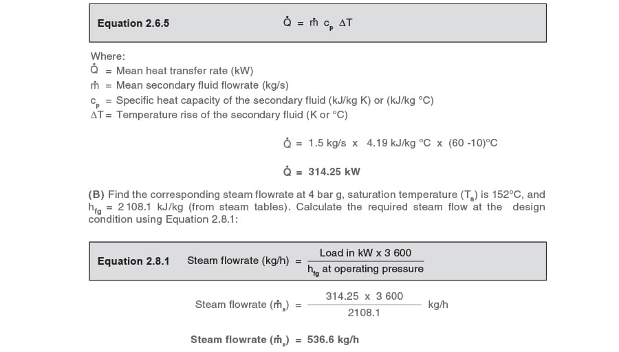
(B) The corresponding steam flowrate.
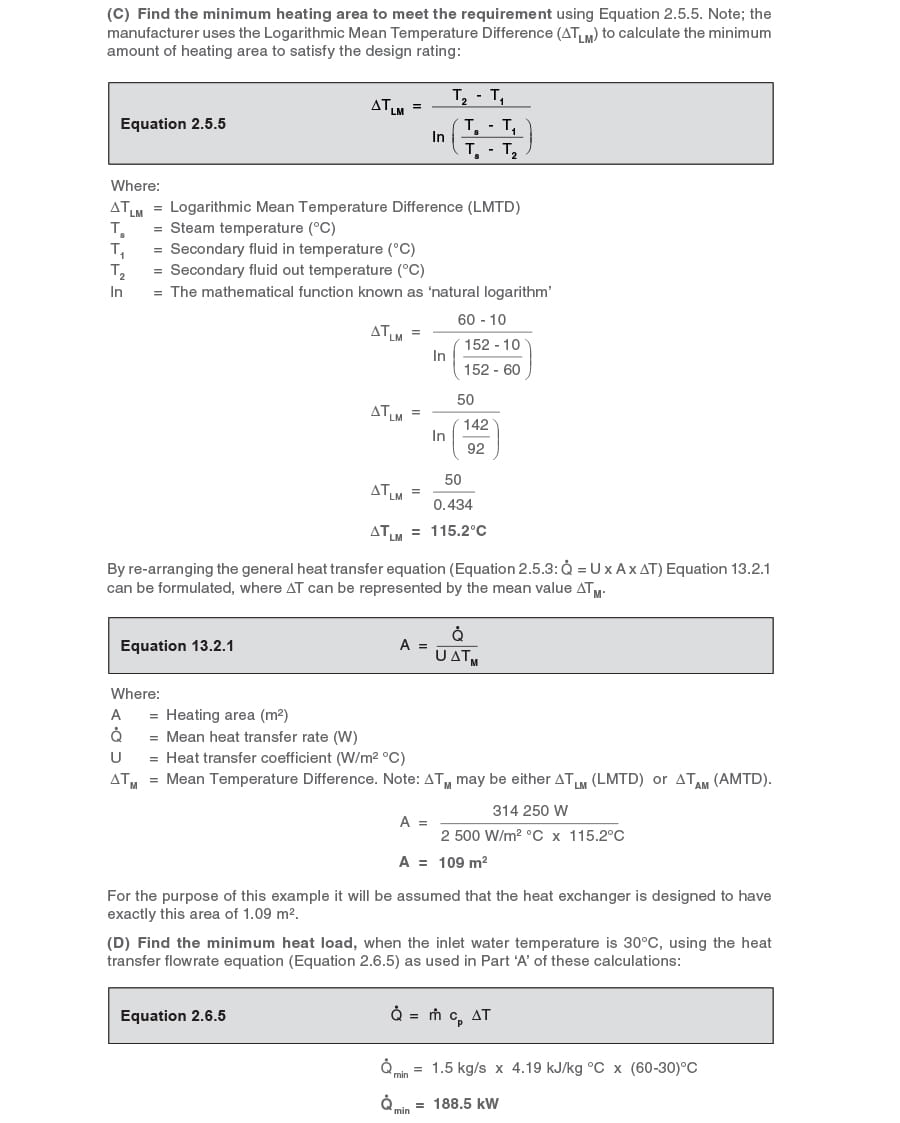
(C) The minimum heating area required.
Also, if the customer’s minimum heat load occurs when the inlet water temperature rises to 30°C, determine:
(D) The minimum heat load.
(E) The corresponding steam pressure in the heat exchanger.
(F) The corresponding steam flowrate.
Calculations:
(A) Find the design heat load using the heat transfer flowrate equation (Equation 2.6.5):
To calculate the corresponding steam flowrate, it is first necessary to determine the steam temperature at the minimum load condition.
It is possible to use the ΔTLM design figures to accurately predict the steam temperature for any load condition, but this requires the use of logarithmic calculations. However, once the exchanger
size is fixed and the design temperatures are known, it is much easier to predict operating temperatures using what could be termed a heat exchanger Temperature Design Constant (TDC).
The TDC method does not require logarithmic calculations. Please note: TDC cannot be used on those applications where the secondary flowrate varies or where control is achieved by varying the condensate level in the steam space.
Note: When sizing a heat exchanger it is normal for heat exchanger manufacturers to use the ΔTLM method. Once sized, by knowing the heating area and the full-load operating temperatures, TDC can be used to accurately predict all operating temperatures resulting from changes in load, as can be seen in the following text.
Operating temperatures can also be predicted graphically by using what is termed a ‘Stall Chart’. This method is discussed in Modules 13.5, 13.6, and 13.7.
Temperature Design Constant (TDC)
For any type of steam-heated exchanger with the secondary liquid flowing at a constant rate, TDC can be calculated from the test figures quoted by the manufacturer for full-load. If these data sets are not available and the heat exchanger is already installed in service, TDC can be calculated by observing the steam pressure (and finding the steam temperature from steam tables) and the corresponding secondary inlet and outlet temperatures at any load.
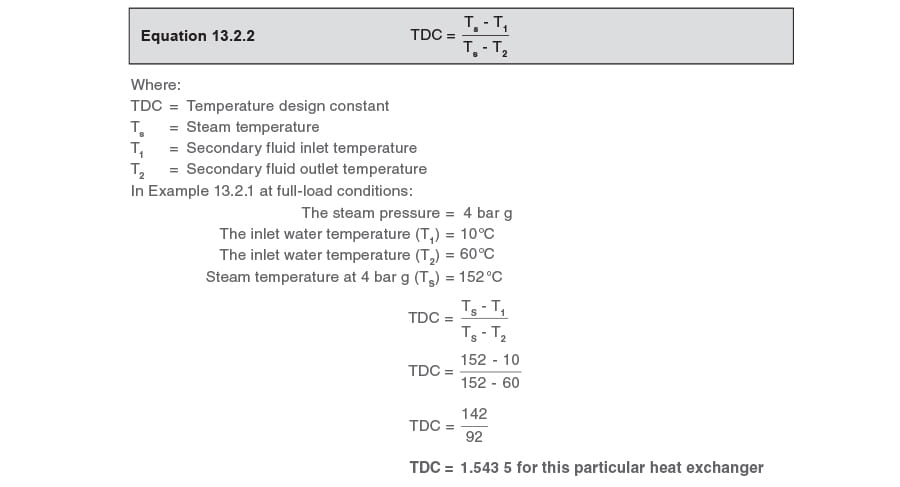
TDC is the ratio of the steam to water temperatures at the inlet and outlet; and is shown in Equation 13.2.2.
The TDC equation can be transposed to find any one variable as long as the other three variables are known. The following equations are derived from the TDC equation (Equation 13.2.2).
To find the steam temperature at any load use Equation 13.2.3:

To find the secondary fluid inlet temperature at any load use Equation 13.2.4:

To find the secondary fluid outlet temperature at any load use Equation 13.2.5:

For any heat exchanger with a constant secondary flowrate, the operating steam temperature can be calculated for any combination of inlet temperature and outlet temperature.
In Example 13.2.1 the secondary outlet temperature remains at 60°C, and minimum load occurs when the inlet temperature is 30°C. What is the steam temperature at minimum load?
Inlet temperature = 30°C
Outlet temperature = 60°C

(E) Find the corresponding heat exchanger steam pressure and enthalpy at minimum load
From steam tables:
A steam temperature of 115.2°C corresponds with a steam pressure of 0.7 bar g.
The specific enthalpy of evaporation at 0.7 bar g (hfg) = 2 215 kJ/kg
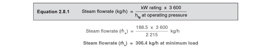
(F) Find the steam flowrate at minimum load:
From (D) the minimum heat load is 188.5 kW.
From (E) the hfg is 2 215 kJ/kg.
Using Equation 2.8.1: