Control Hardware Electric-Pneumatic Actuation

Contents
Controllers and Sensors
Controllers and sensors are important parts of the control system; without information from the sensor, the controller cannot make a decision and instruct the valve to move. This tutorial briefly discusses the different types of controllers and sensors available and how they operate. A brief explanation of digital and analogue control signals is also given.
Controllers
It is important to state at the outset that not all control applications need a sophisticated controller.
An on/off valve and actuator, for example, can be operated directly from a thermostat. Another example is the operation of high limit safety controls, which have a ‘snap’ action to close valves or to switch off fuel supplies.
However, when the control requirements become more sophisticated, a controller is needed to match these requirements.
The controller receives a signal, decides what action is needed and then sends a signal to the actuator to make it move.
In the age of the microchip, integrated circuits and computers, the functions performed by the controller can be very complex indeed.
However, since an analogy between the human brain and controllers/computers has been made in previous Modules, the renowned IBM motto can be paraphrased:
Computer - Fast, accurate and stupid
Human being - Slow, slovenly and brilliant
To summarise, the controller will not solve all problems. It must be properly selected and commissioned, subjects which will be dealt with later.
Although most controllers are now electronic digital/microprocessor based, a range of pneumatic controllers is commercially available. These might be used in hazardous areas where the risk of explosion precludes the use of electrics/electronics. It is possible to make electrical equipment ‘intrinsically safe’ or explosion-proof or flameproof, however, there is usually a substantial cost implication.
As previously mentioned, the functions carried out by the controller can be very complex and it is beyond the scope of this publication to list them in detail, or to explain how they operate.
The major variations that require consideration are as follows:
Single loop controller
Operates one valve/actuator from a single sensor.
Multi-loop controller
May operate more than one valve/actuator from more than one sensor.
Single input/output
Can accept only one signal from the sensor and send only one to the actuator.
Multi-input/output (multi-channel)
Can accept several signals and send out several signals.
Real time
May include a time clock to switch at pre-determined, pre-set times.
Elapsed time
May switch at some predetermined, pre-set length of time before or after other items of plant have been switched on or off.
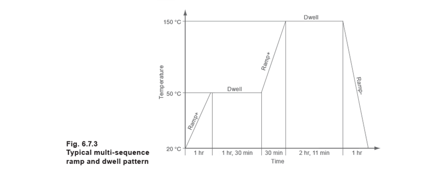
Ramp and dwell
Using temperature as an example, the capability to raise the temperature of a controlled medium over a specified time period and then to hold it at a pre-set value. Such controllers frequently incorporate a series of ramps and dwells.
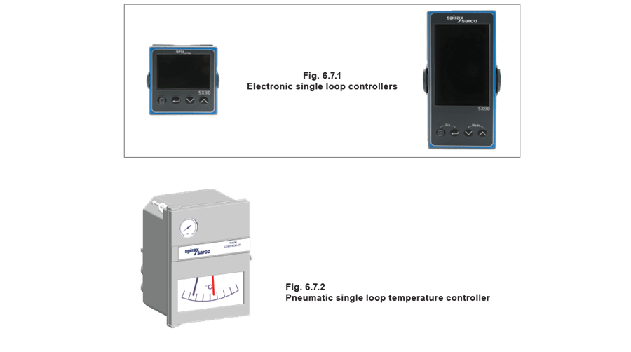
Figure 6.7.1, shows a typical electronic, single loop controller. This has P + I + D action (discussed in Modules 5.2 and 5.4), suitable for 110 or 230 volt supply.
Figure 6.7.2 shows a pneumatic single loop controller with P action.
Different models can be selected to control either temperature or pressure.
A single loop controller, which has the ability to perform ramp and dwell functions, may have a typical sequence pattern like the one shown in Figure 6.7.3. This shows a series of ramps (temperature change) and dwell (maintaining temperature) functions, carried out over a period of time
One term frequently found in control literature is ‘Programmable Logic Controller (PLC)’. In a batch process, the controller must trigger a sequence of actions, for example, turning valves or pumps on or off. In some cases the whole sequence is on a timed basis, but often the various steps may be triggered by a specific condition being reached and maintained for a certain time period; for example a certain temperature being reached or a vessel filled. These sequences can be controlled by a PLC, a microcomputer-based device that utilises standard interfaces for sensors and actuators to control the process.
Another type of complex controller is the plant room controller, which might be used to control the boiler, pump, heating control valve, HWS valve, as well as providing a number of other features.
Sensors
In this Section the subject of temperature measurement will be covered more broadly. There are a wide variety of sensors and transducers available for measuring pressure, level, humidity, and other physical properties. The sensor is the part of the control system, which experiences the change in the controlled variable.
The sensor may be of a type where a change in temperature results in a change of voltage or perhaps a change in resistance.
The signal from the sensor may be very small, creating the need for local signal conditioning and amplification to read it effectively. A small change in resistance signalled by a sensor in response to a change in temperature, may, for example, be converted to an electrical voltage or current for onward transmission to the controller.
The transmission system itself is a potential source of error.
Wiring incurs electrical resistance (measured in ohms), as well as being subject to electrical interference (noise). In a comparable pneumatic system, there may also be minute leaks in the piping system.
The term ‘thermostat’ is generally used to describe a temperature sensor with on/off switching.
‘Transducer’ is another common term, and refers to a device that converts one physical characteristic into another; for example, temperature into voltage (millivolts).
An example of a transducer is a device that converts a change in temperature to a change in electrical resistance.
With pneumatic devices, the word ‘transmitter’ is frequently encountered. It is simply another description of transducer or sensor, but usually with some additional signal conditioning.
However, the actual measuring device is usually termed as the sensor, and the more common types will be outlined in the following Section.
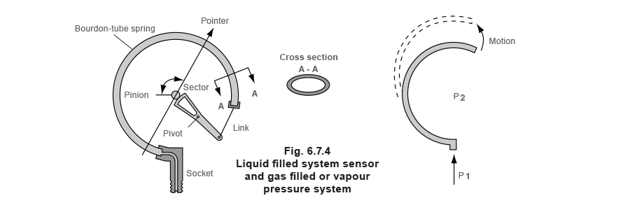
Filled system sensors
With pneumatic controllers, filled system sensors are employed. Figure 6.7.4 illustrates the principles of such a system.
One term frequently found in control literature is ‘Programmable Logic Controller (PLC)’. In a batch process, the controller must trigger a sequence of actions, for example, turning valves or pumps on or off. In some cases the whole sequence is on a timed basis, but often the various steps may be triggered by a specific condition being reached and maintained for a certain time period; for example a certain temperature being reached or a vessel filled. These sequences can be controlled by a PLC, a microcomputer-based device that utilises standard interfaces for sensors and actuators to control the process.
Another type of complex controller is the plant room controller, which might be used to control the boiler, pump, heating control valve, HWS valve, as well as providing a number of other features.
When the temperature changes, the fluid expands or contracts, causing the Bourdon tube to tend to straighten out. Sometimes a bellows is used instead of a Bourdon tube.
In the past, the filling has often been mercury. When heated, it expands, causing the Bourdon tube to uncoil; cooling causes contraction and forces the Bourdon tube to coil more tightly. This coil movement is used to operate levers within the pneumatic controller enabling it to perform its task. A pressure sensing version will simply utilise a pressure pipe connected to the Bourdon tube. Note: for health and safety reasons, mercury is now used less often. Instead, an inert gas such as nitrogen is often employed.
Resistance temperature detectors (RTDs)
RTDs (Figure 6.7.5) employ the fact that the electrical resistance of certain metals change as the temperature alters. They act as electrical transducers, converting temperature changes to changes in electrical resistance. Platinum, copper, and nickel are three metals that meet RTD requirements and Figure 6.7.6 shows the relationship between resistance and temperature.
A resistance temperature detector is specified in terms of its resistance at 0°C and the change in resistance from 0°C to 100°C. The most widely used RTD for the typical applications covered in these Modules are platinum RTDs. These are constructed with a resistance of 100 ohms at 0°C and are often referred to as Pt100 sensors. They can be used over a temperature range of -200°C to +800°C with high accuracy (±0.5%) between 0°C and 100°C.
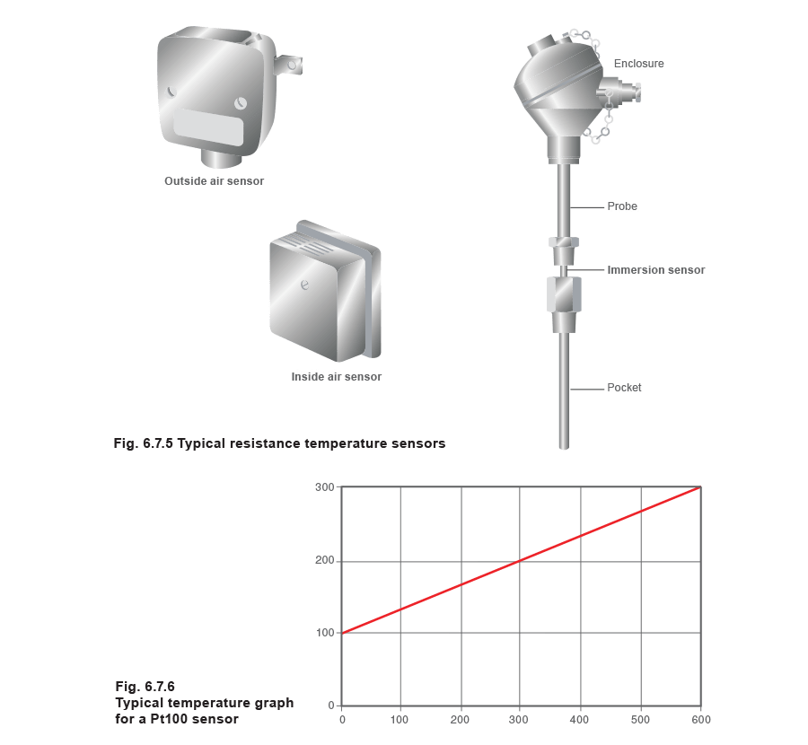
As can be seen from Figure 6.7.6, the increase of resistance with temperature is virtually linear. Pt100s have a relatively small change in resistance, which requires careful measurement. Resistance in the connecting cables needs to be properly compensated for.
Thermistors
Thermistors use semi-conductor materials, which have a large change in resistance with increasing temperature, but are non-linear. The resistance decreases in response to rising temperatures (negative coefficient thermistor), as shown in Figure 6.7.7.

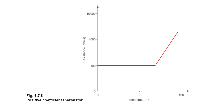
Positive coefficient thermistors can be manufactured where the resistance increases with rising temperature (Figure 6.7.8) but their response curve makes them generally unsuitable for temperature sensing.
Thermistors are less complex and less expensive than RTDs but do not have the same high accuracy and repeatability. Their high resistance means that the resistance of the connecting cable is less important.
Thermocouples
If two dissimilar metals are joined at two points and heat is applied to one junction (as shown in Figure 6.7.9), an electric current will flow around the circuit. Thermocouples produce a voltage corresponding to the temperature difference between the measuring junction (hot) and the reference junction (cold).
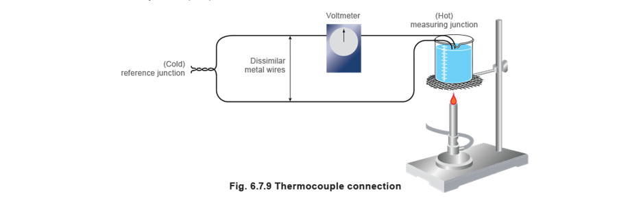
The cold reference junction temperature must be accurately known if the thermocouple itself is to provide accurate sensing.
Traditionally, the cold junction was immersed in melting ice (0°C), but the temperature of the cold junction is now measured by a thermistor or an RTD and, from this, the indicated temperature, generally at the measuring junction, is corrected. This is known as cold junction compensation.
Any pair of dissimilar metals could be used to make a thermocouple. But over the years, a number of standard types have evolved which have a documented voltage and temperature relationship. The standard types are referred to by the use of letters, that is, Type J, K, T and others.

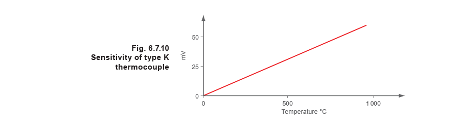
The most widely used general-purpose thermocouple is Type K.
The dissimilar metals used in this type are Chrome (90% nickel, 10% chromium) and Alumel (94% nickel, 3% manganese, 2% aluminium and 1% silicon) and can be used between the range 0°C to 1 260°C. Figure 6.7.10 illustrates the sensitivity of Type K thermocouples, and it can be seen that the output voltage is linear across the complete range.
Thermocouples are available in a wide variety of sizes and shapes. They are inexpensive and rugged and reasonably accurate, with wide temperature ranges. However, the reference junction temperature must be held at a constant value otherwise deviations must be compensated for. The low junction voltages mean that special screened cable and careful installation must be used to prevent electrical interference or ‘noise’ from distorting signals.
Example 6.7.1
Imagine two people, person A and person B, each on opposite hilltops and each with a flag and a flag-pole. The aim is for person A to communicate to person B by raising his flag to a certain height. Person A raises his flag half way up his pole. Person B sees this and also raises his flag halfway. As person A moves his flag up or down so does person B to match. This would be similar to an analogue system.
Example 6.7.2
Now assume that person A does not have a pole but instead has two boards, one with the figure ‘0’ and the other with the figure ‘1’, and again wants person B to raise his flag half way, that is to a height of 50% of his flag-pole. The binary number for 50 is 110010, so he displays his boards, two at a time, in the corresponding order. Person B reads these boards, translates them to mean 50 and raises his flag exactly half way. This would be similar to a digital system.
It can be seen that the digital system is more precise as the information is either a ‘1’ or a ‘0’ and the position can be accurately defined. The analogue example is not so precise because person B cannot determine if person A’s flag is at exactly 50%. It could be at 49% or 51%. It is for this reason, together with higher integration of microprocessor circuitry that digital sgnals are becoming more widely used.
Digital addressing
Digital addressing allows a controller to send information over a set of wires onto which several receivers are connected and yet be able to communicate with only one of those receivers if required. This is done by allocating an address to each receiver, which the controller must broadcast first.
To explain this, consider the digital example above but now assume that there is another person, person C on a third hill. Person B and person C can both see person A, so person A must first indicate to whom he is communicating.
This is done with the first board. If the first board is a ‘0’ then all subsequent data is intended for person B who adjusts his flag accordingly. Conversely, if the first board is a ‘1’ then all subsequent data is intended for person C. Hence person B has a digital address of ‘0’ and person C has a digital address of ‘1’; each person knows that the first number to be seen by them refers to the address not the message.
HART®, PROFIBUS® and Foundation™ Fieldbus.
HART® stands for ‘Highway Addressable Remote Transducer’ and is a standard originally developed as a communications protocol for control field devices operating on a 4-20 mA control signal. The HART® protocol uses 1200 baud Frequency Shift Keying (FSK) based on the Bell 202 standard to superimpose digital information on the conventional 4-20 mA analogue signal. Maintained by an independent organisation, the HART® Communication Foundation, the HART® protocol is an industry standard developed to define the communications protocol between intelligent field devices and a control system.
What is PROFIBUS®?
PROFIBUS® is an open fieldbus standard for a wide range of applications in manufacturing and process automation independent of manufacturers. Manufacture independence and transparency are ensured by the international standards EN 50170, EN 50254 and IEC 61158.
It allows communication between devices of different manufacturers without any special interface adjustment. PROFIBUS® can be used for both high-speed time critical applications and complex communication tasks. PROFIBUS® offers functionally graduated communication protocols DP and FMS. Depending on the application, the transmission technologies RS-485, IEC 1158-2 or fibre optics can be used.
It defines the technical characteristics of a serial Fieldbus® system with which distributed digital programmable controllers can be networked, from field level to cell level. PROFIBUS® is a multi-master system and thus allows the joint operation of several automation, engineering or visualization systems with their distributed peripherals on one bus.
At sensor/actuator level, signals of the binary sensors and actuators are transmitted via a sensor/actuator bus. Data are transmitted purely cyclically.
At field level, the distributed peripherals, such as I/O modules, measuring transducers, drive units, valves and operator terminals communicate with the automation systems via an efficient, real-time communication system. As with data, alarms, parameters and diagnostic data can also be transmitted cyclically if necessary.
At cell level, programmable controllers such as PLC and IPC can communicate with each other. The information flow requires large data packets and a large number of powerful communication functions, such as smooth integration into company-wide communication systems, such as Intranet and Internet via TCP/IP and Ethernet.
What is Foundation™ Fieldbus?
Foundation™ Fieldbus is an all-digital, serial, two-way communications system that serves as a Local Area Network (LAN) for factory/plant instrumentation and control devices. The Fieldbus® environment is the base level group of the digital networks in the hierarchy of plant networks. Foundation™ Fieldbus is used in both process and manufacturing automation applications and has a built-in capability to distribute the control application across the network.
Unlike proprietary network protocols, Foundation™ Fieldbus is neither owned by any individual company, nor regulated by a single nation or standards body. The Foundation™ Fieldbus, a not-for-profit organization consisting of more than 100 of the world’s leading controls and instrumentation suppliers and end users, controls the technology.
While Foundation™ Fieldbus retains many of the desirable features of the 4-20 mA analogue system, such as a standardized physical interface to the wire, bus-powered devices on a single wire, and intrinsic safety options, it also offers many other benefits.
Device interoperability
Foundation™ Fieldbus offers interoperability; one Fieldbus® device can be replaced by a similar device with added functionality from a different supplier on the same Fieldbus® network while maintaining specified operations. This permits users to ‘mix and match’ field devices and host systems from various suppliers. Individual Fieldbus® devices can also transmit and receive multivariable information, and communicate directly with each other over a common Fieldbus®, allowing new devices to be added to the Fieldbus® without disrupting services.
Enhanced process data
With Foundation™ Fieldbus, multiple variables from each device can be brought into the plant control system to analyse trends, optimise processes, and generate reports. Access to accurate, high-resolution data enables processes to be fine-tuned for better productivity, less downtime, and higher plant performance.
Overall view of the process
Modern Fieldbus® devices, with powerful microprocessor-based communications capabilities, permit process errors to be recognized faster and with greater certainty. As a result, plant operators are notified of abnormal conditions or the need for preventive maintenance, allowing personnel to consider pro-active decisions. Lower operating efficiencies are corrected more quickly, enabling production to rise while raw material costs and regulatory problems fall.
Improved in plant safety
Fieldbus technology helps manufacturing plants keep up with stringent safety requirements. It can provide operators with earlier warning of potential hazardous conditions, thereby allowing corrective action to be taken to reduce unplanned shutdowns. Enhanced plant diagnostic capabilities also offer less frequent access to hazardous areas, thus minimizing the risks to personnel.
Easier predictive maintenance
Enhanced device diagnostics capabilities make it possible to monitor and track insidious conditions such as valve wear and transmitter fouling. Plant personnel are able to perform predictive maintenance without waiting for a scheduled shutdown, thus reducing or even avoiding downtime.
Reduced wiring and maintenance costs
The use of existing wiring and multi-drop connections provides significant savings in network installation costs. This includes reductions in intrinsic safety barriers and cabling costs, particularly in areas where wiring is already in situ.
Additional cost savings can be achieved through the decreased time required for construction and start-up, as well as simplified programming of control and logic functions using software control blocks built into Fieldbus® devices.