Desuperheating

Contents
Other Types of Desuperheater
Venturi type desuperheaters
The venturi type desuperheater employs a restriction in the superheated steam pipeline to create a region of high velocity and turbulence where the cooling water is injected. This helps to establish intimate contact between the steam and the cooling water, improving the efficiency of the desuperheating process.
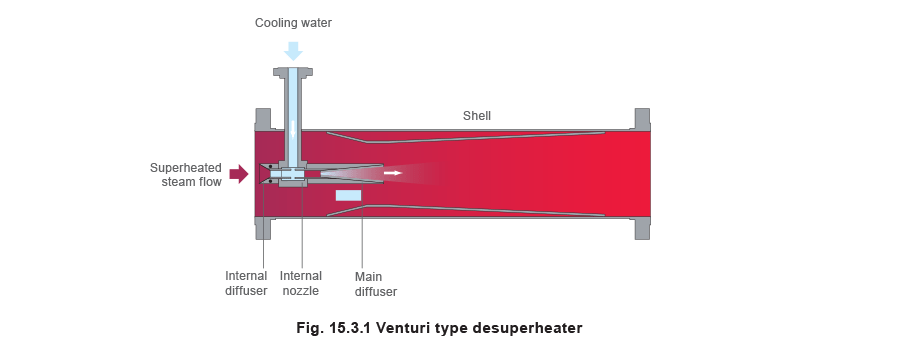
The desuperheating process is carried out in two separate phases:
- The first stage of desuperheating occurs in the internal diffuser. A portion of the steam is accelerated in the internal nozzle and the velocity is used to atomise the incoming water. The cooling water is injected into the diffuser through a number of small jets, which helps to further atomise the water.
- In the second stage of desuperheating, a saturated mist or fog emerges from the internal diffuser into the main diffuser where it mixes with the remainder of the steam.
The main diffuser itself creates a restriction to the remainder of the steam thereby increasing its velocity in this region. Thus, there is a region of turbulence where the second stage of desuperheating occurs. This mechanism minimises cooling water contact with the sidewalls, combining maximum desuperheating effectiveness with minimum pipe wear.
The steam flow turndown ratio does vary depending on the actual conditions, but 4:1 is typical.
In applications where there is a dedicated pressure reducing station upstream of the desuperheater, the available steam turndown can be improved to over 5:1.
The cooling water turndown is usually satisfactory for most plant applications, with 20:1 possible depending on the actual operating conditions. At cooling water turndowns beyond 20:1, the need for a cooling water booster pump also increases.
Venturi type desuperheaters can be installed either horizontally or vertically with the steam flow upwards. When installed vertically, better mixing occurs which can result in an improved turndown ratio of over 5:1. The main problem with this is ensuring that there is enough vertical space to install the desuperheater, as it will be more than several metres long.
A modification to the standard venturi type desuperheater is the attemperator desuperheater. Thisessentially uses the same method of injecting the coolant into the superheated steam, but does not utilise the venturi shaped mixing section. Attemperator desuperheaters are used in place of the venturi type where there is sufficient space available to install a long absorption pipe, especially where slightly higher turndown is required, but where the additional cost of a steam atomising type cannot be justified.
The term attemperator is also generally used to refer to a desuperheater that is installed after a boiler or superheater to give accurate control over temperature and pressure.
Advantages:
- Steam turndown ratios of up to 5:1 and cooling water turndowns of over 20:1.
- Simple operating principle (although more complex than the spray type).
- No moving parts.
- Accurate control of desuperheated steam temperature; typically within 3°C of the saturation temperature.
- Suitable for operation under steady or variable steam conditions.
- There is reduced wear in the downstream pipework compared to a spray type desuperheater, as the cooling water emerges as a mist rather than as a spray.
Disadvantages:
- Pressure drop is incurred (although this is generally small and within acceptable limits).
- The absorption length is still longer than the steam atomising type; so more space is required for installation.
- A minimum cooling water flow rate is required.
Applications:
- Suitable for most general plant applications, except where high turndowns on steam flowrate are required
Steam atomising desuperheaters
Steam atomising desuperheaters employ a high-pressure auxiliary steam supply to atomise the incoming cooling water.
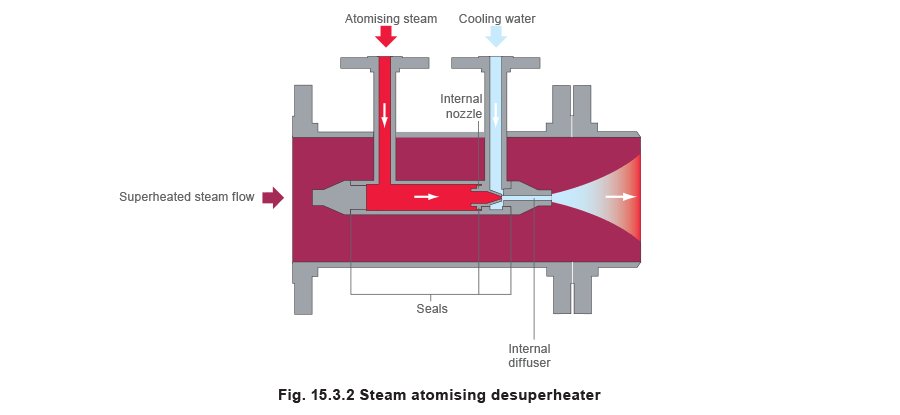
The desuperheating process occurs in two stages:
The first stage occurs in the diffuser, where the cooling water is atomised by the high velocity atomising steam. The auxiliary steam pressure needs to be at least 1.5 times the desuperheater inlet pressure, typically with a minimum pressure of 4 bar a. The flowrate of atomising steam is normally between 2% and 5% of the mainline flow. The use of atomising steam means that the cooling water can be introduced into the diffuser at lower pressures. In general, the only requirement is that the pressure must be greater than that of the superheated steam.
In the second stage, a wet mist or fog emerges from the diffuser where it mixes with the mainline steam in the pipeline. Evaporation occurs in the pipework immediately downstream of the desuperheater, where the remaining water droplets remain suspended in the steam and gradually evaporate.
Using steam to atomise the cooling water produces finely atomised water particles, which ensures efficient heat transfer and evaporation.
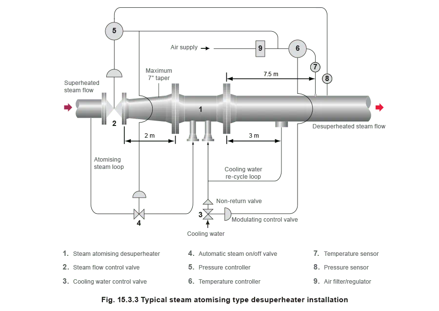
This arrangement allows for high steam turndown ratios; ratios of up to 50:1 are possible. It should however be noted that at turndowns greater than 20:1, low pipeline velocities may result in the ‘settling out’ of water, caused by the decreasing momentum of the water droplets. In this case, a drainage and recycle arrangement is required (see Figure 15.3.3). If such a recycle arrangement cannot be fitted, the turndown ratio will be reduced.
The typical installation of a steam atomising desuperheater is illustrated in Figure 15.3.3.
Advantages:
- Good turndown – steam turndown of up to 50:1 is possible, but operation and control is most efficient for a turndown of around 20:1.
- Very compact – with a short absorption length relative to the other types.
- Pressure drop is negligible.
- The cooling water used can be cold, as the atomising steam will preheat it.
- Low approach to saturation temperature – typically to within 6°C of saturation temperature.
Disadvantages:
- Auxiliary high pressure steam is required.
- The amount of extra equipment required and the additional pipework is relatively expensive.
Applications:
- Suitable for applications where the steam flowrates will vary widely, for example in combined pressure reducing and desuperheating stations.
Variable orifice desuperheater
The variable orifice desuperheater controls the flow of cooling water into the mainline by a free-floating plug placed in the flow.
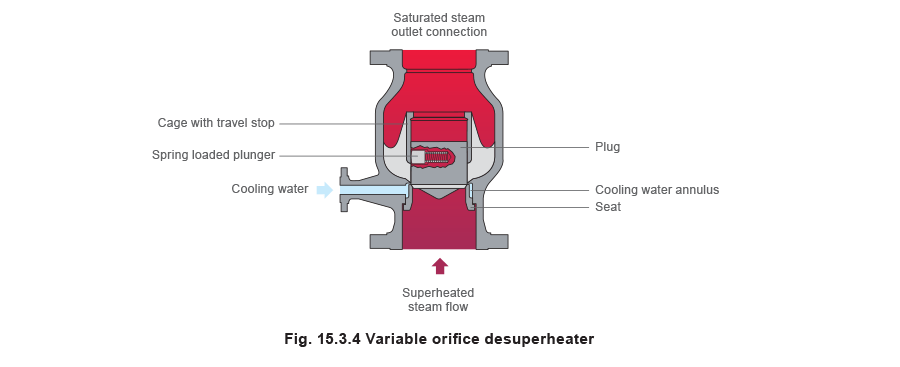
The variable orifice desuperheater consists of a plug that moves up and down in a cage. This movement is limited by a travel stop incorporated into the top of the cage. Its position within the cage depends on the flow of superheated steam in the mainline.
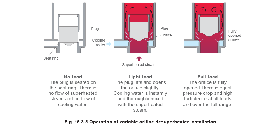
Under no-flow conditions, the plug rests on a seat ring, surrounded by an annulus of cooling water. When superheated steam starts to flow through the desuperheater, the plug is forced off the seat by the steam pressure. As the flow increases, the plug is lifted further away from the seat, thereby creating a variable orifice between the plug and the seat. The increase in velocity between the plug and the seat creates a pressure drop across the annulus, drawing water into the superheated steam flow.
The low pressure drawing the water into the pipeline also helps to atomise the water into a fine mist. The turbulence associated with the change in velocity and direction of the steam assists in mixing the coolant and the steam. Vortices created immediately upstream of the plug ensure that the coolant is completely mixed with the steam.
The efficient mixing of the coolant and the superheated steam within the desuperheater body means that the absorption length is relatively short, and the temperature sensing element may be installed within 4 or 5 metres of the desuperheater body.
The rate at which cooling water enters the annulus is varied by a control valve that is regulated as a function of the downstream temperature.
The plug is typically fitted with a spring-loaded plunger, which increases the friction between the plug and the cage, effectively damping the plug’s movement. Given a fixed pressure drop across the valve this effectively enables the amount of cooling water to be varied when mixing with the flow of superheated steam.
The plunger also provides stability under light load conditions.
The fact that the coolant is not sprayed into the desuperheater, and that virtually all the desuperheating occurs in the body of the device, means that there is little wear of associated pipework or the desuperheater itself. Therefore, thermal sleeves are unnecessary.
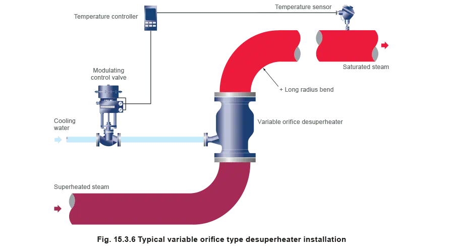
A typical installation of a variable orifice desuperheater is illustrated in Figure 15.3.6
Advantages:
- The turndown is only limited by the cooling water control valve, and steam turndown ratios of up to 100:1 can be readily achieved.
- Low approach to saturation temperature – typically to within 2.5°C of saturation temperature.
- Short absorption length.
- The cooling water pressure need only be 0.4 bar superior to the superheated stem pressure.
- Superheated steam velocities may be very low.
Disadvantages:
- Significant pressure drop across the desuperheater.
- Relatively higher cost.
- The desuperheater has to be installed vertically. If a bend is located immediately after the outlet, it must have a long radius.
Applications:
- Suitable for applications where the steam flowrate will vary widely and a relatively high pressure drop is not critical.
- Where the steam velocity is likely to be very low.
Combined pressure control valve and desuperheater
In some instances, it is convenient to integrate the pressure control valve and the desuperheater into one unit.
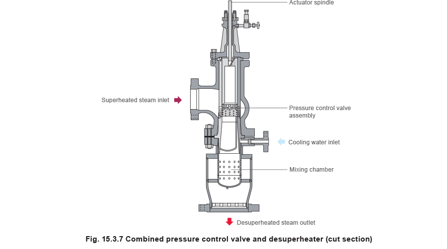
The pressure reducing aspect is similar to a standard pressure reducing valve. Although a number of different designs of pressure reducing valve could be used, angle or globe configurations are most commonly used. In addition, the valve is typically of the balanced type (with either a balancing plug or a balanced bellows arrangement) to reduce the required actuator force.
As accurate pressure control is usually important in desuperheater applications, pneumatic actuation of the valve is virtually universal, and so is the use of positioners. In addition, because quite substantial pressure drops may be involved, the manufacturer will often offer a noise reduction trim for the pressure control valve (see Figure 15.3.8).

The desuperheating aspect will also vary depending on the application, but it is common for a multiple point radial injection type to be used. The mixing of the coolant and the steam is improved due to the high velocity of the superheated steam after the pressure-reducing valve. Radial injection type desuperheaters have the advantage that they can be easily combined with the pressure reducing valve to produce a single unit.
In some combined pressure control and desuperheating stations, there are a number of baffle plates installed immediately after the desuperheating station. These plates induce further pressure drop and improve mixing of the steam and coolant.
Combined pressure control valve and desuperheating stations are commonly used in turbine bypasses, where the valve dumps the flow directly to the condenser or to ‘cold reheat’.
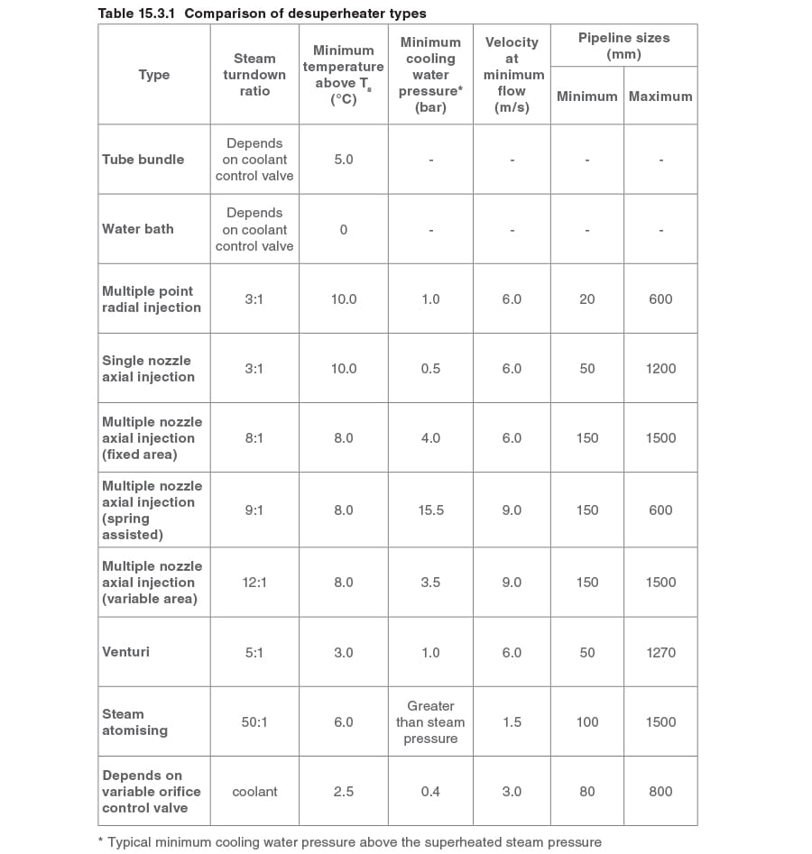
Comparison of types of desuperheater
Table 15.3.1 compares the typical performance and installation characteristics of the different desuperheater types. It should be noted that these properties may vary between different manufacturers, and indeed, they may depend on the particular operating conditions of the system.