Desuperheaters

Contents
Typical Installations
A number of important considerations need to be taken into account when installing desuperheaters. This tutorial covers issues such as water quality and pressure control. A desuperheater selection chart and a list of applications are also included.
Installation
There are a number of important considerations to take into account when installing a desuperheater,
namely:
- The properties of the cooling water.
- The installation of the desuperheater itself.
- The ancillary a required.
- The control valves used on the cooling water line and the superheated steam line.
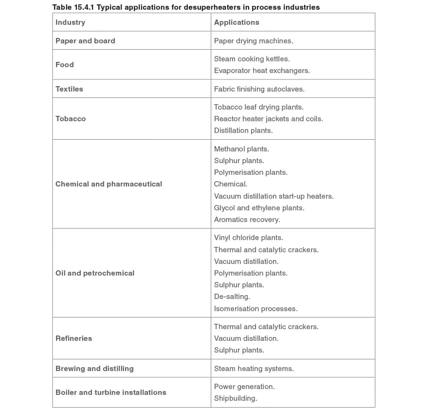
A generalised installation of an in-line desuperheater is shown in Figure 15.4.1.
Properties of the cooling water:
- Temperature - The most effective desuperheating will be achieved using cooling water that is hot, preferably as close to the saturation temperature as possible. However, cooling water temperatures as low as 5°C could be used if absolutely necessary.
The use of hot water has the following advantages:
- It minimises the time period for which water particles are suspended in the steam.
- It evaporates more quickly.
- It minimises the amount of water falling to the inside walls of the pipework.
There are however, two disadvantages to using high temperature cooling water:
- The higher the temperature of the cooling water, the greater the required flowrate due to its lower cooling effect.
- Unless a supply of the water at the required temperature is available, additional heating mechanisms may have to be incorporated.
Due to the benefits of using hot water, it is logical to insulate the hot water supply pipes to minimise heat loss, and to protect personnel.
- Quality - The quality of the injected water is important. The Total Dissolved Solids (TDS) content of the injection water should be as low as possible, as any solids that come out of solution will be deposited on:
- The faces of valves.
- The small orifices in the desuperheater nozzles.
- The inner side of the piping downstream of the desuperheater.
In addition to reducing the TDS levels, all cooling water should be passed through a suitable deaerator and strainer installed before the water control valve. The deaerator will deoxygenate the water, thus reducing the potential of oxygen corrosion in the system.
- Pressure and flowrate - As mentioned in Module 15.2, the pressure of the cooling water, along with the area of the nozzles, determines the flow of cooling water into the desuperheater. Table 15.3.1 shows the typical minimum pressures (above the superheated steam pressure) required for each type of desuperheater. It should be noted that these might vary between manufacturers and for different steam pressures.
If a booster pump is used, a ‘spill back line’ will be required to ensure that there is always sufficient flow through the pump at times of low cooling water demand.
- Control - A pressure drop will inevitably be required over the water control valve. When using cooling water close to saturation temperature, care is needed to ensure that the pressure drop is not large enough to cause the water to flash into steam.
An equal percentage characteristic plug in the water control valve may be selected, which will usually complement the pump characteristic.
- Source - The availability of water at high pressure and temperature may be difficult. There are a number of possible sources of the cooling water; and options include:
- Water from the pressure side of the boiler feedpump (providing the boiler uses modulating level control).
- De-mineralised water.
- Condensate.
- Town water. This however may require treatment to improve the quality, otherwise salts may be deposited on the inside of the desuperheater downstream pipework.
Desuperheater installation
The total installed length of a desuperheater station will vary with size and type, but it is typically about 7.5 m.
Most desuperheaters can be installed in any direction (the variable orifice type is a notable exception), but if installed vertically, the flow should be upwards.
The venturi type is best installed in a vertical pipe with the flow in the upward direction, as this aids mixing of the water and the steam. However, such installations are not usually possible due to the vertical space required.
Superheated steam pressure control
Although it is possible to design desuperheater installations to operate with varying upstream pressures, it is much simpler if a constant supply pressure is maintained.
The amount of cooling water added is controlled by the temperature of the steam after the desuperheater. The higher the temperature, the more the control valve will open, and the greater the amount of water added. The target is to reduce the steam temperature to within a small margin of the design discharge temperature.
If the superheated steam supply pressure is increased, the saturation temperature will also increase.
However, the set value on the coolant controller will not change, and an excessive amount of water will be added, resulting in wet steam. Pressure sensors used in the control of the superheated steam pressure should ideally be located at the point of use, so that the pressure control valve can compensate for any line loss between the desuperheater and the point of use.
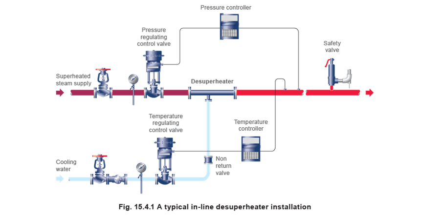
Temperature sensor positioning
The minimum distance from the point of water injection to the temperature sensing point is critical:
- If the sensor is too close to the water injection point, the mixing of the steam and the water will not have been completed, and the temperature sensor will give a false output.
- If the sensor is too far away, it will make the installation unnecessarily long.
The minimum installation distance will vary between different types of desuperheater and with different manufacturers. It is usually specified as a function of the temperature difference between
the required outlet temperature and either the inlet temperature or the coolant temperature.
Figure 15.4.2 shows a typical manufacturer’s sensor positioning chart.
Separator station
Efficient drainage of the pipework following the desuperheater is essential. To ensure that water cannot accumulate at any point, the pipe should be arranged to fall approximately 20 mm per metre in the direction of flow, and should be provided with a separator station.
The steam trap used to drain the separator should be carefully selected to prevent air binding, and the discharge pipe from the steam trap should have ample capacity to deal with the drainage and it should be fixed as near to vertical as possible. In addition, there must be sufficient space in the drainage pipe for the water to flow down and air to pass up the pipe. The steam trap must also be able to withstand superheat conditions.
On critical applications, for example, prior to a turbine, a separator is even more important; the separator station will remove entrained water in the case of control failure, and prevent too much water being added to the steam.
Isolation valves
To allow maintenance to be safely carried out, isolation valves are recommended upstream of:
- The superheated steam pressure control valve.
- The desuperheater.
- The cooling water supply.
Typically, these should be installed approximately, but no less than 10 pipe diameters from the item they are isolating.
Safety valve
A safety valve may be required to protect equipment downstream of the desuperheating station from overpressure, in the event of failure of the pressure control station.
It is necessary to ensure discharge pipework from the safety valve is led away to a safe area. This is of particular importance as high temperature superheated steam may be discharged.
Temperature and pressure ratings
Most equipment to be used on steam systems is designed with saturated steam in mind. It is therefore important that all equipment used in a desuperheater station will tolerate both the maximum temperature and pressure of the superheated steam.
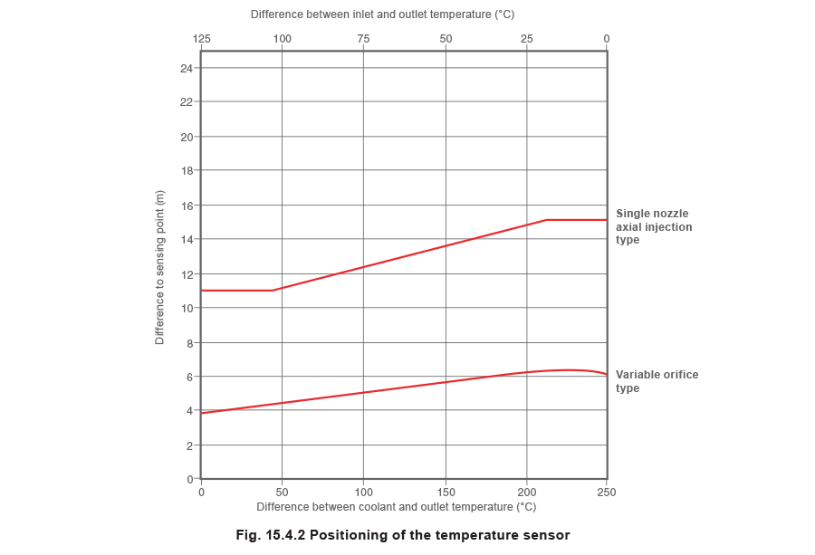
Most equipment will have specified pressure and temperature limitations that are based on the nominal pressure (PN) rating of the material and the specific design of the device. By definition, the PN rating is the maximum pressure that a material can withstand at 120°C. For example, a PN16 rating means that the material will withstand a pressure of 16 bar g at 120°C. At higher temperatures, the maximum pressure will decrease, however, the exact relationship varies and depends on the material.
Figure 15.4.3 depicts typical pressure / temperature gradients for PN16, PN25 and PN40 rated products on a non-specific material. It is important to note that different materials will, by specification, produce variations in the temperature gradient.
In addition, components such as gaskets, fasteners and internal components may have a further limiting effect on the maximum temperature and pressure.
Controls
The selection and installation of the control devices to be used in a desuperheater station are an important consideration, as they can affect the overall turndown of the desuperheater. If the controls installed have a lower turndown ratio than the desuperheater itself, the turndown of the desuperheater station will be reduced (refer to Module 15.2).
Further information on basic control theory and practice can be found in Blocks 5 to 8 inclusive.
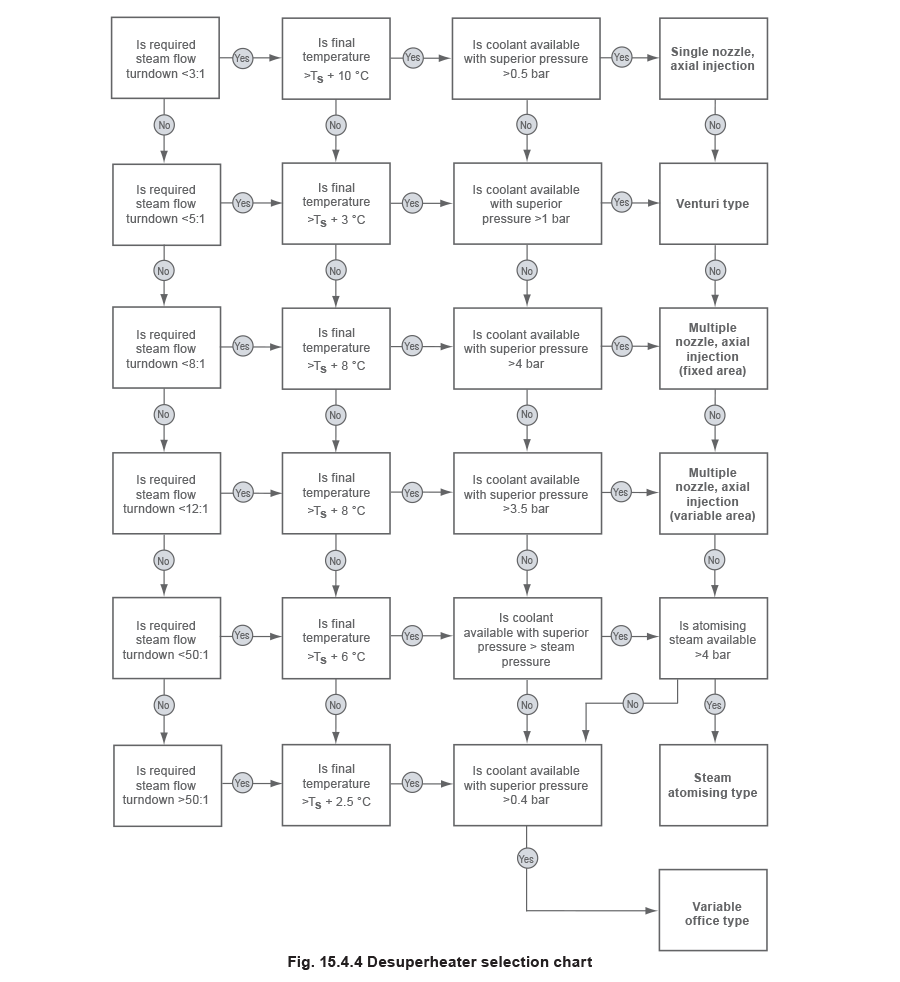
Selection
When selecting a suitable type of desuperheater for a particular application, the following factors need to be considered:
- Turndown - This is probably one of the most important considerations, as the different types of desuperheater vary significantly in the range of superheated steam flowrates that can be effectively desuperheated.
It is important to note here that, although ensuring that the device will have sufficient turndown for the flow likely to be encountered, it is important not to specify more turndown capability than is really needed. This predominantly affects cost, but it can also lead to poor system performance. Poor performance is often aggravated by the fact that most desuperheaters tend to perform better at the higher end of the specified flowrates and a system designer would tend to allow for increases in capacity due to expansion. As an extreme example, if the maximum flow specified was ten times the current requirement (in order to take into account future growth), the desuperheater will operate between 1 and 10% of its full flowrate instead of the 10% to 100% it is designed for.
- Desuperheated steam temperature - As seen in the previous Module, different types of desuperheater are capable of reducing the steam temperature to within several degrees of the saturation temperature. For example, if desuperheated steam temperatures within 5°C of the saturation temperature (TS) were required, a venturi or variable orifice type desuperheater would be selected (see Table 15.3.1).
Generally, where some degree of residual superheat can be tolerated, the desuperheated steam temperature should be as high above saturation as possible. This is beneficial for several reasons:
- Cost - a close approximation to saturation temperature is generally only achievable with the more costly types of desuperheaters.
- Controller sensitivity - this may be a problem where the desuperheated steam temperature is required to be close to the saturation temperature. Limited controller sensitivity is one of the reasons why most desuperheaters are limited in their approach to saturation temperature. For example, if a controller had a sensitivity of ±5°C, it would not be able to distinguish between saturation temperature and 5°C above. If such a controller interpreted the steam temperature at 5°C above TS, and the steam were actually at TS, it would increase the flow of cooling water. But since the temperature of the saturated steam will not decrease (due to the latent heat of evaporation), the controller will add increasingly more coolant as it would still believe the system to be at 5°C above TS. This will result in very wet steam flooding the steam main after the desuperheater station.
- It becomes increasingly difficult to evaporate the cooling water as the superheated steam temperature drops towards saturation, due to the reduced temperature difference between the two.
- The lower temperature difference also reduces the heat transfer rate between the water and the steam, and therefore the water droplets have to stay in suspension for longer to be evaporated. This increases the likelihood that the water particles will fall out of suspension in the pipe. In order to prevent this from occurring, as the temperature approaches TS, the velocity of the steam needs to be increased in order to create more turbulence.
- Available coolant supply pressure - The choice of desuperheater type will also depend on the availability of cooling water at the necessary pressure. It would provide a cost advantage to use cooling water that is already available, for example, from the pressure side of a boiler feedwater pump.
If the available pressure were not sufficient for a particular type of desuperheater, additional pumping arrangements would have to be made.
A typical manufacturer’s selection chart is shown in Figure 15.4.4. It is based on the typical performance and installation characteristics, which can be found in Table 15.3.1.
The method used to size a desuperheater will vary depending on the particular manufacturer and the type of desuperheater, and therefore it is outside the scope of this publication.
Typical applications
Desuperheaters are mainly applied in two areas:
- Power generation - Desuperheaters are mainly used to reduce the temperature of steam emitted from turbine bypass systems to an efficient level for operation on other parts of the plant requiring saturated steam for heat transfer purposes.
- Process industry - In process industries, desuperheaters are used as part of a system for reducing the temperature and pressure of steam from boilers to economical levels of operation. Table 15.4.1 shows some common application examples in particular industries.