Flowmetering

Contents
Installation
System design, installation and maintenance considerations for steam flowmeters, including the use of strainers, separators and flow straighteners, together with piping layouts. Includes a useful checklist for selecting the correct type of flowmeter for an application.
Installation
The manufacturer should always supply installation data with the product as this will lay down specific requirements such as the minimum lengths of unobstructed pipe to be provided upstream and downstream of the flowmeter. It is usual for the flowmeter supplier to be able to offer advice and relay recommendations regarding the installation requirements of his particular flowmeter.
Statistics show that over a third of flowmeter problems are due to poor installation. No steam flowmeter, however good its design and thorough its manufacture, can cope if little attention is paid to its installation and the layout of the steam system.
Steam quality
Dry steam
Steam should always be provided in as dry a condition as possible at the point of metering.
Module 4.4 has already demonstrated that wet steam will cause inaccuracies and can physically damage some types of flowmeter.
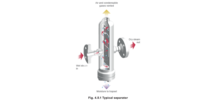
A simple but effective method of drying wet steam is to install a separator upstream of the flowmeter.
Entrained moisture impinges on the baffle plates and the heavy droplets fall to the bottom and are drained away via a properly sized and selected steam trap set. Independent tests show that it is possible to achieve a 99% dryness fraction over a wide range of flows by use of a high efficiency separator as shown in Figure 4.5.1.
The separator has one other important benefit: Slugs of water impacting on any steam flowmeter (i.e. waterhammer) can cause severe mechanical damage. Fitting a separator before a steam flowmeter will reduce the resulting impact pressure from water slugs by up to 90%, affording considerable protection to any expensive flowmetering device.
The separator with its drain trap ensures efficient condensate removal ahead of the flowmeter.
But any low points where the steam main rises to a higher level should also have drain trap points that are adequately sized and correctly selected.
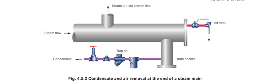
It is also worthwhile ensuring that air and other entrained gases are removed by fitting an air vent in the steam line.
The separator shown in Figure 4.5.1 has a top connection suitable for an automatic air vent that will help to remove incondensable gases prior to the flowmetering station. Figure 4.5.2 illustrates a combined drain trap point and venting station at the end of a steam main.
Clean steam
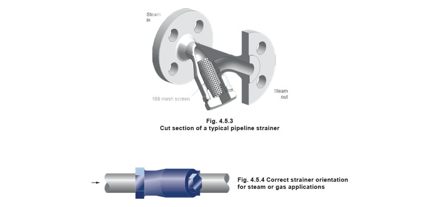
A pipeline strainer (Figure 4.5.3) should be fitted ahead of the flowmeter. This will remove any larger pieces of scale, swarf or other pipeline debris, which would other wise damage the primary device. The internal strainer device should be cleaned periodically, particularly during the initial start-up of a new installation.
As with any steam pipeline strainer, the strainer should be installed with the body horizontal to avoid creating an accumulation of condensate and hence a reduction in the screening area (Figure 4.5.4).
Maintenance
The provision of valves either side of the flowmeter should be considered for isolation purposes, since inspection, maintenance and perhaps even ‘removal for calibration’ will sometimes be necessary. Such valves should be of the fully open or fully closed type, which present the least resistance to flow, such as full bore ball valves. In addition, a valved bypass, or a make-up piece to act as a temporary replacement if the flowmeter is removed from the pipeline, will solve the problem of interrupting the steam supply during maintenance procedures. Both pipework and flowmeter must be adequately supported and properly aligned with a slight fall to the last drain point ahead of the flowmeter. Pipework should also be properly and effectively insulated to minimise radiation losses and further condensation.
Installation recommendations
- Ensure all pipework is adequately supported and properly aligned. - This will prevent waterlogging during shutdown periods and possible problems on ‘start-up’.
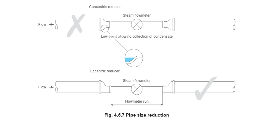
- Size the flowmeter on capacity rather than line size. - Where a pipe size reduction is necessary, use eccentric reducing sockets.
- Take care to observe the correct direction of flow. - An arrow on the flowmeter body should show this.
- It is advisable to fit a check valve downstream of the transducer. - This will avoid possible damage by reverse flow.
- Do not close-couple the flowmeter immediately downstream to a pressure reducing valve. - This comment is particularly relevant to pilot operated self-acting pressure controllers with a narrow proportional band; these may cause pressure oscillations leading to inaccuracies and/or possible damage of the primary unit.
As a general rule, a self-acting pressure control should be at least 10, and preferably 25 pipe diameters upstream of the flowmeter. - Do not install the flowmeter downstream of a partially open stop valve. - This can lead to swirl, which may lead to inaccuracies.
- A separator should always be fitted upstream of the flowmeter. - This will remove entrained moisture from the steam. Dry steam is required for accurate steam flowmetering. It will also provide some degree of protection against waterhammer impact damage.
The separator should be drained using a float thermostatic steam trap. - A full line size strainer with 100 mesh stainless steel screen must be fitted. - This will prevent dirt and scale reaching the transducer. This is especially advisable on old or dirty systems where dirt or corrosion is present.
- Ensure gasket faces do not protrude into the pipeline.
- A bellows sealed stop valve may be fitted upstream of the flowmeter.
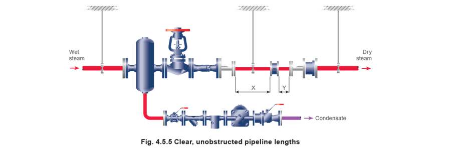
- Recommended lengths of clear, unobstructed pipe must be provided upstream and downstream of the flowmeter.
X + Y is known as the ‘Flowmeter run’ (Figure 4.5.5).
The question of leaving sufficient length of clear, unobstructed pipework upstream and downstream of the flowmeter is most important. This is to prevent the risk of swirl, which can be produced by bends and partially open valves.
Some types of flowmeter are more susceptible to swirl than others. Some manufacturers recommend the use of flow straighteners to remove swirl (Figure 4.5.6). However, it is preferable to do all that is possible to prevent the risk of swirl by providing an adequate flowmeter run since flow straighteners in steam systems can entrain surface water. It may even be preferable to select a steam flowmeter that is less susceptible to the effects of swirl.

Correct sizing of the flowmeter is also essential and most manufacturers will recommend maximum and minimum flowrates for each size of flowmeter.
If the flowmeter to be used is smaller than the pipeline into which it is to be fitted, reductions in pipe size should be achieved by using eccentric reducers (Figure 4.5.7). This will prevent the collection of condensate at a lowpoint - as would be the result if concentric reducers were used. The reduction in pipe size should be achieved at the nearest point to the flowmeter consistent with maintaining the required flowmeter run.
System design considerations
Adopting a structured approach to steam flowmetering will help to ensure that:
- The design objectives are achieved.
- No elements of the design are omitted.
- The benefits are maximised.
- The financial outlay is minimised.
There are two main elements to such an approach:
- Consideration of the existing steam supply system
The planner should identify any future changes to the plant or process that may affect the installation of steam flowmeters, and should consider whether the installation of flowmeters is likely to act as a catalyst for such changes. Alterations to the system, for example, may involve blanking off redundant sections of steam mains, rerouting pipework, or generally improving the condition of pipe layout and / or insulation. - Identifying the aim of installing steam flowmetering
Typically, one or more of the following design criteria will be clearly defined:
- To provide information for accounting purposes, such as departmental allocation of costs.
- To facilitate custody transfer, for example where a central station sells steam to a range of clients.
- To facilitate Monitoring and Targeting (M and T) policies and observe trends.
- To determine and monitor energy utilisation and efficiency.
Each of the above criteria imposes different limitations on the design of the steam flowmetering system.
If flowmetering is to be used for accounting purposes or for custody transfer, it will be necessary to install a sufficient number of flowmeters for consumption to be assigned to each of the cost centres. Also, if the product being sold is energy not steam, flowmeters will also have to be installed on the condensate return lines, as this hot water will have a heat value. For both applications, the highest possible standard of flowmetering will be required, particularly with respect to accuracy, turndown ratio, and repeatability.
The system may also require check flowmetering so that consumption can be proven correct. It should be noted that confidence in any monitoring system, once lost, is very difficult to restore. A system should also include measurement of the system losses incurred as a result of supplying steam to a particular location. This implies that flowmeter positions should be located as near to the boiler house as possible.
In M and T applications and in the determining of energy efficiency, the important flowmetering criterion is repeatability. The user will be more interested in trends in consumption rather than absolute values.
Determining flowmeter arrangements
Once the system layout has been determined, and the data required to accurately measure the energy consumption of the system / plant has been decided, the number and location of required flowmeters can be contemplated. This requires consideration of the site as a whole including the steam main from the boiler house.
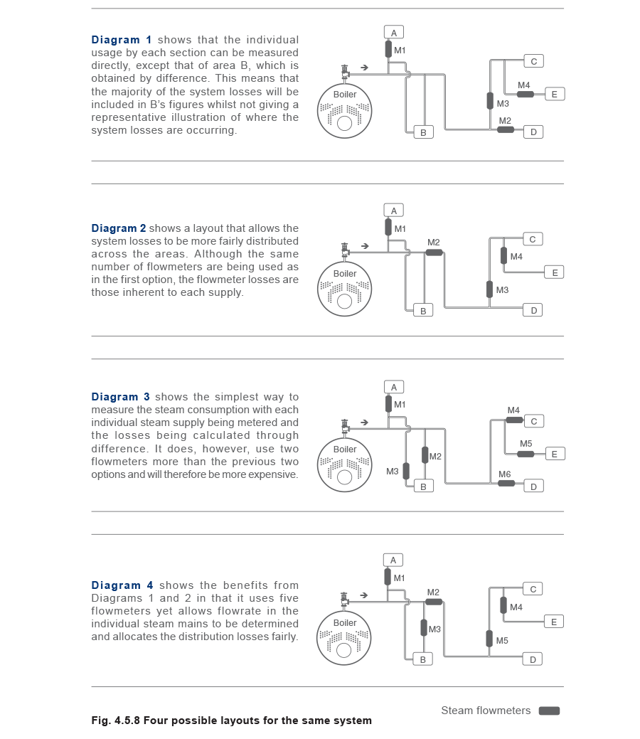
Figure 4.5.8 shows four possible layouts for the same system.
The four diagrams shown in Figure 4.5.8 illustrate how the connection of multiple steam flowmeters can affect the results obtained and ultimately influence the data analysis.
Specifying a steam flowmeter
Some of the factors which need to be taken into account when selecting a steam flowmeter include:
Performance
- Accuracy.
- Repeatability.
- Turndown.
- Pressure drop.
- Display unit facilities.
Maintenance
- Reliability.
- Calibration needs.
- Spare parts requirement or service exchange scheme.
- Ease of maintenance.
Cost
- Cost of flowmeter.
- Cost of associated instruments.
- Cost of installation.
- Overall lifetime costs.
Other factors
- Reputation of manufacturer.
- Back-up provided by the manufacturer.
- Initial calibration requirements.
- Density compensation.
- Ability to interface.
- Availability of associated equipment.
- Quality of literature and information provided.
The above points should be considered collectively. For example, it can be a mistake to simply select a flowmeter on accuracy when, often, there is a balance between accuracy and reliability.
The most accurate flowmeters are often the most delicate and can suffer badly when used with steam. A more sensible approach will be to look for reasonable accuracy with good repeatability and proven reliability with steam.
Useful checklist to help in the selection of a steam flowmeter
The following is offered to help in the selection of a steam flowmeter and gives a useful check list and prompt for the questions that need to be raised:
- What is the application? (Boiler house flowmeter, departmental flowmeter, or plant flowmeter.)
- What is the pipeline size and configuration?
- What is the steam pressure and temperature?
- What is the object of flowmetering? (Cost allocation, plant efficiency check, energy saving scheme monitor.)
- What is the flowmeter required to indicate? (Flowrate, quantity, mass or volume.)
- Is there a need to measure maximum, minimum, and/or average flowrates?
- What accuracy, repeatability and turndown is needed?
- What is the purchase budget allowed?
- How much of this is allocated to installation costs and ancillary equipment costs?
- Who will install the flowmeter?
- Who will commission the flowmeter?
- Who will maintain the flowmeter?
- Is there a need to interface the flowmeter with any local chart recorders or central energy management systems?
- Is physical size a constraint?
- Is the flowmeter designed for operation with steam?
- Are any other features required, such as remote alarms on timers?
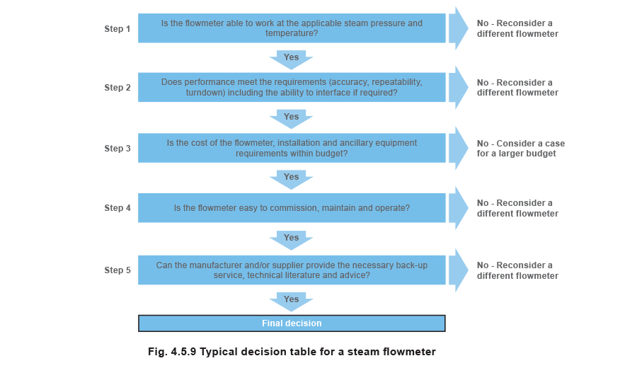
Once this evaluation has been completed, the Steps in Figure 4.5.9 need to be followed before making a final selection.
Conclusion
Difficulties in the energy management of steam arise from the fact that it is often perceived as a ‘free’ (unmetered) service.
Measurement is essential if savings are to be made
Most plants have figures on the annual cost of fuel. However, even these figures can become doubtful when a supply provides fuel to multi-users. Again, measuring the total fuel consumption of two or more perhaps dissimilar boilers can hide useful information.
Gas or oil can be measured quite easily. Measurement of steam is more difficult - which explains why steam is often perceived as being free. If steam is metered, then is the measurement accurate? Most flowmeters depend on a measurement of volume, whilst steam is traditionally costed on a mass basis. To ensure the correct volumetric flowrate is measured for conversion to mass flow, density compensation is essential.
It is easy to accept the instrument reading as shown by the integrator or chart. Most flowmeters, however, are calibrated on media other than steam, with a correction factor to convert the scale reading to an actual amount. It is important the manufacturer can provide test details if required.
Flowmeters should be checked from time to time to make sure that there is no erosion to any measuring orifice or any similar change to an alternative type of primary device.
Although steam flowmetering is often confined to the boiler house, it can be extremely useful in other parts of the system. It is essential where steam has to be costed. It is essential information for the plant manager charged with conserving energy or improving production efficiency or quality.
Steam flowmeters will provide useful information on plant performance, fouling of heat transfer surfaces or the malfunction of steam traps.
Flowmeter readings provide the only positive approach when schemes or improvements are introduced to save steam.