Flowmetering

Contents
Types of Steam Flowmeter
The operation, advantages and limitations of different types of steam flowmeter, including orifice plate, variable area and vortex shedding devices.
There are many types of flowmeter, those suitable for steam and condensate applications include:
- Orifice plate flowmeters.
- Turbine flowmeters (including shunt or bypass types).
- Variable area flowmeters.
- Spring loaded variable area flowmeters.
- Direct in-line variable area (TVA) flowmeters.
- Ultrasonic flowmeters.
- Vortex shedding flowmeters
Each of these flowmeter types has its own advantages and limitations. To ensure accurate and consistent performance from a steam or condensate flowmeter, it is essential that it is correctly matched to the intended application.
This Module will review the above flowmeter types, and discuss their characteristics, their advantages and disadvantages, typical applications and typical installations.
Orifice plate flowmeters
The orifice plate is one in a group known as head loss devices or differential pressure flowmeters. In simple terms the pipeline fluid is passed through a restriction, and the pressure differential is measured across that restriction. Based on the work of Daniel Bernoulli in 1738 (see Module 4.2),
the relationship between the velocity of fluid passing through the orifice is proportional to the square root of the pressure loss across it. Other flowmeters in the differential pressure group include venturis and nozzles.
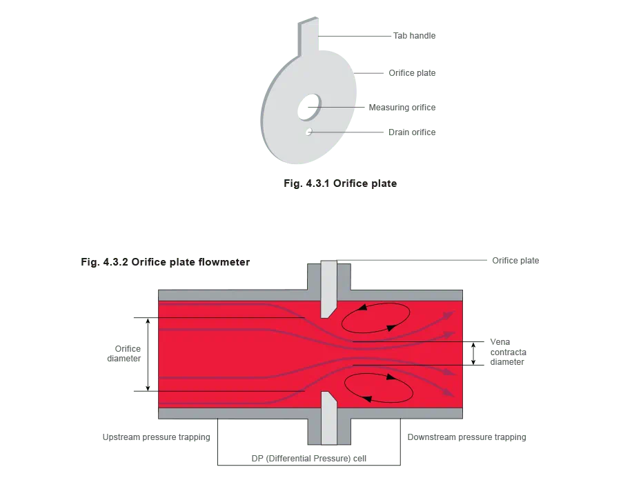
With an orifice plate flowmeter, the restriction is in the form of a plate which has a hole concentric with the pipeline. This is referred to as the primary element.
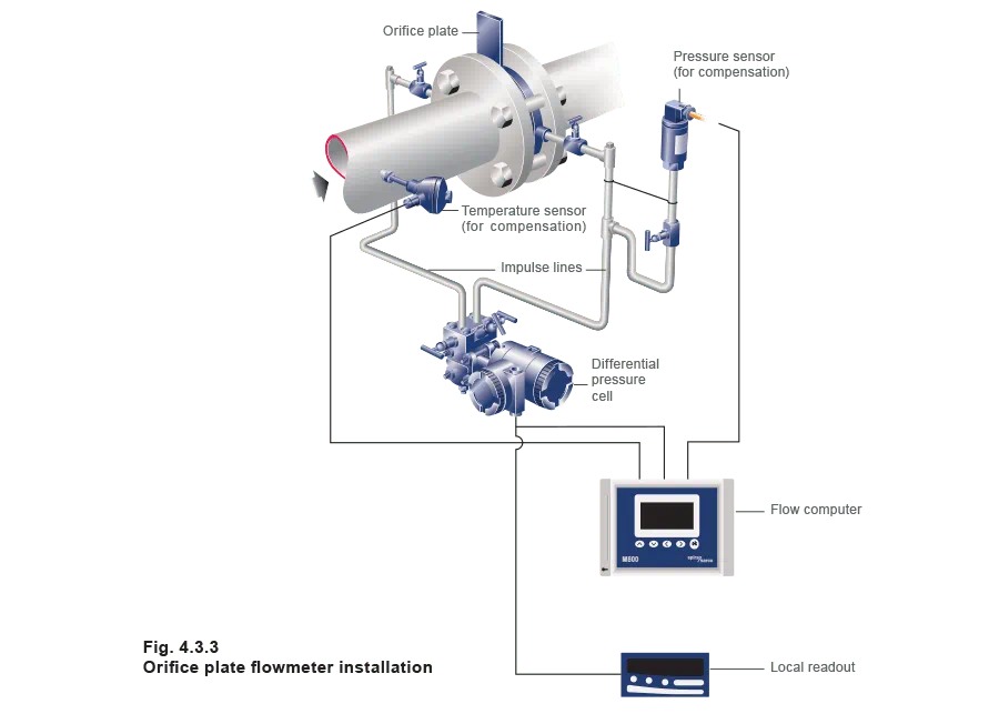
To measure the differential pressure when the fluid is flowing, connections are made from the upstream and downstream pressure tappings, to a secondary device known as a DP (Differential Pressure) cell.
From the DP cell, the information may be fed to a simple flow indicator, or to a flow computer along with temperature and/or pressure data, which enables the system to compensate for changes in fluid density.
In horizontal lines carrying vapours, water (or condensate) can build up against the upstream face of the orifice. To prevent this, a drain hole may be drilled in the plate at the bottom of the pipe. Clearly, the effect of this must be taken into account when the orifice plate dimensions are determined.
Correct sizing and installation of orifice plates is absolutely essential, and is well documented in the International Standard ISO 5167.
Installation
A few of the most important points from ISO 5167 are discussed below:
Pressure tappings - Small bore pipes (referred to as impulse lines) connect the upstream and downstream pressure tappings of the orifice plate to a Differential Pressure or DP cell.
The positioning of the pressure tappings can be varied. The most common locations are:
- From the flanges (or carrier) containing the orifice plate as shown in Figure 4.3.3. This is convenient, but care needs to be taken with tappings at the bottom of the pipe, because they may become clogged.
- One pipe diameter on the upstream side and 0.5 x pipe diameter on the downstream side. This is less convenient, but potentially more accurate as the differential pressure measured is at its greatest at the vena contracta, which occurs at this position.
Corner tappings - These are generally used on smaller orifice plates where space restrictions mean flanged tappings are difficult to manufacture. Usually on pipe diameters including or below DN50.
From the DP cell, the information may be fed to a flow indicator, or to a flow computer along with temperature and/or pressure data, to provide density compensation.
Pipework - There is a requirement for a minimum of five straight pipe diameters downstream of the orifice plate, to reduce the effects of disturbance caused by the pipework.
The amount of straight pipework required upstream of the orifice plate is, however, affected by a number of factors including:
- The ß ratio; this is the relationship between the orifice diameter and the pipe diameter (see Equation 4.3.1), and would typically be a value of 0.7.

- The nature and geometry of the preceding obstruction. A few obstruction examples are shown in Figure 4.3.4:
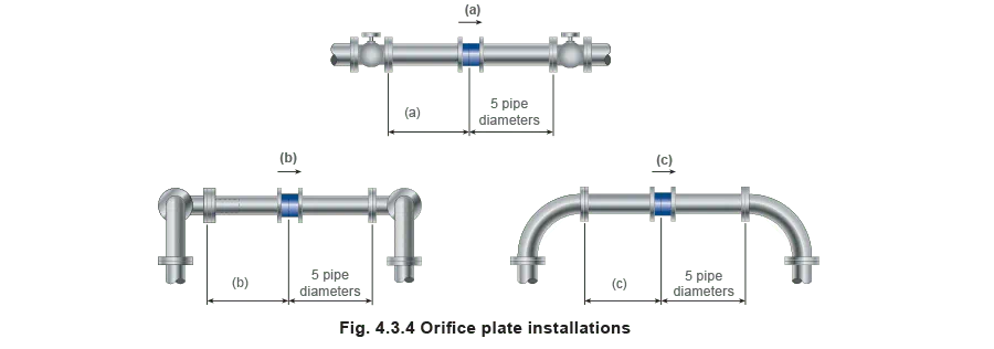
Table 4.3.1 brings the ß ratio and the pipework geometry together to recommend the number of straight diameters of pipework required for the configurations shown in Figure 4.3.4.
In particularly arduous situations, flow straighteners may be used. These are discussed in more detail in Module 4.5.

Advantages of orifice plate steam flowmeters:
- Simple and rugged.
- Good accuracy.
- Low cost.
- No calibration or recalibration is required provided calculations, tolerances and installationcomply with ISO 5167.
Disadvantages of orifice plate steam flowmeters:
- Turndown is limited to between 4:1 and 5:1 because of the square root relationship between flow and pressure drop.
- The orifice plate can buckle due to waterhammer and can block in a system that is poorly designed or installed.
- The square edge of the orifice can erode over time, particularly if the steam is wet or dirty. This will alter the characteristics of the orifice, and accuracy will be affected. Regular inspection and replacement is therefore necessary to ensure reliability and accuracy.
- The installed length of an orifice plate flowmetering system may be substantial; a minimum of 10 upstream and 5 downstream straight unobstructed pipe diameters may be needed for accuracy.
This can be difficult to achieve in compact plants. Consider a system which uses 100 mm pipework, the ß ratio is 0.7, and the layout is similar to that shown in Figure 4.3.4(b):
The upstream pipework length required would be = 36 x 0.1 m = 3.6 m
The downstream pipework length required would be = 5 x 0.1 m = 0.5 m
The total straight pipework required would be = 3.6 + 0.5 m = 4.1 m
Typical applications for orifice plate steam flowmeters:
- Anywhere the flowrate remains within the limited turndown ratio of between 4:1 and 5:1.
This can include the boiler house and applications where steam is supplied to many plants, some on-line, some off-line, but the overall flowrate is within the range.
Turbine flowmeters
The primary element of a turbine flowmeter consists of a multi-bladed rotor which is mounted at right angles to the flow and suspended in the fluid stream on a free-running bearing. The speed of rotation of the turbine is proportional to the velocity, and hence volumetric flowrate of the fluid being measured. By knowing the density of the fluid, mass flowrate can then be calculated if required.
The speed of rotation of the turbine may be determined using an electronic proximity switch mounted on the outside of the pipework, which counts the pulses, as shown in Figure 4.3.5.

Turbine flowmeters for liquids (condensate)
Turbine flowmeters for liquids, such as condensate, are typically designed with the diameter of the rotor slightly less than the inside diameter of the flowmetering chamber.
In larger pipelines, to minimise cost, the turbine element can be installed in a pipework bypass, or even for the flowmeter body to incorporate a bypass or shunt, as shown in Figure 4.3.6.
Bypass flowmeters comprise an orifice plate, which is sized to provide sufficient restriction for a sample of the main flow to pass through a parallel circuit. Whilst the speed of rotation of the turbine may still be determined as explained previously, there are many older units still in existence which have a mechanical output as shown in Figure 4.3.6.
Clearly, friction between the turbine shaft and the gland sealing can be significant with this mechanical arrangement.
Insertion turbine flowmeters for steam, gas and liquids:
Insertion type turbine flowmeters are becoming increasingly popular: their main advatage being that they can be installed under full process conditions, without the need to shut down the process line. This is achieved through ‘hot tapping’. Their principle of operation remains the same as for liquid turbine flowmeters where the rotational frequency of the rotor blades is measured using a magnetic pick-up sensor.
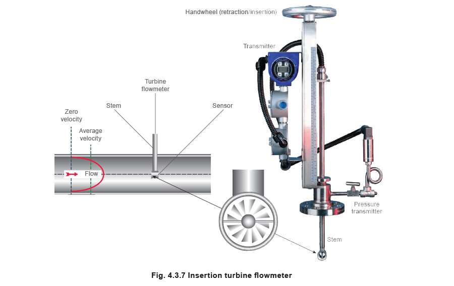
The insertion turbine flowmeter measures the ‘point velocity’ in a pipe and microprocessor electronics then uses a profile factor to relate the point velocity to the average velocity in the pipe. The flow computer continuously updates this profile factor based on the point velocity and diameter of the pipe. Once the average velocity is known, volumetric flowrate can be calculated using the flow area of the pipe. Adding a temperature or pressure sensor allows the flowmeter to measure density of the fluid and calculate mass flow.
Advantages of insertion turbine flowmeters:
- Can be installed under full process conditions.
- Relatively in-expensive on larger pipelines.
- Can be used on all media.
- Low induced pressure drop as there is minimal flow obstruction.
- Moderate accuracy, typically ±2% of reading (steam) and ±1.5% (condensate).
- Accurately measure flowrate up to a turndown of 25:1
- Relatively compact installation lengths, typically requiring only 10D and 5D of straight pipework upstream and downstream of the flowmeter respectively.
Can measure flowrate in large pipelines (> DN400)
Disadvantages of insertion turbine flowmeters:
- Relatively expensive when used on smaller pipes.
- Moving parts require regular maintenance.
- Wet steam can damage the turbine and affect accuracy.
Typical applications for insertion turbine flowmeters:
- Dry saturated steam
- Superheated steam.
- Condensate return lines, however, care must be taken to remove air and flash steam prior to flowmetering.
- Gas and air applications.
Variable area flowmeters
The variable area flowmeter (Figure 4.3.8), often referred to as a rotameter, consists of a vertical, tapered bore tube with the small bore at the lower end, and a float that is allowed to freely move in the fluid. When fluid is passing through the tube, the float’s position is in equilibrium with:
- The dynamic upward force of the fluid.
- The downward force resulting from the mass of the float.
- The position of the float, therefore, is an indication of the flowrate.
In practice, this type of flowmeter will be a mix of:
- A float selected to provide a certain weight, and chemical resistance to the fluid.
The most common float material is grade 316 stainless steel, however, other materials such as Hastalloy C, aluminium or PVC are used for specific applications.
On small flowmeters, the float is simply a ball, but on larger flowmeters special shaped floats are used to improve stability.
- A tapered tube, which will provide a measuring scale of typically between 40 mm and 250 mm over the design flow range.
Usually the tube will be made from glass or plastic. However, if failure of the tube could present a hazard, then either a protective shroud may be fitted around the glass, or a metal tube may be used.
With a transparent tube, flow readings are taken by observation of the float against a scale. For higher temperature applications where the tube material is opaque, a magnetic device is used to indicate the position of the float.
Because the annular area around the float increases with flow, the differential pressure remains almost constant.

Advantages of variable area flowmeters:
- Linear output.
- Turndown is approximately 10:1.
- Simple and robust.
- Pressure drop is minimal and fairly constant.
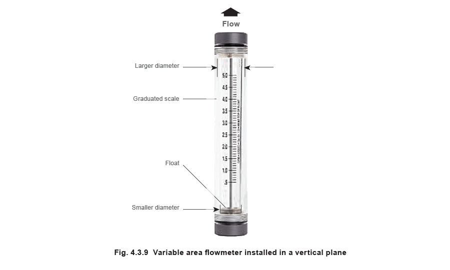
Disadvantages of variable area flowmeters:
- The tube must be mounted vertically (see Figure 4.3.9).
- Because readings are usually taken visually, and the float tends to move about, accuracy is only moderate. This is made worst by parallax error at higher flowrates, because the float is some distance away from the scale.
- Transparent taper tubes limit pressure and temperature.
Typical applications for variable area flowmeters:
- Metering of gases
- Small bore airflow metering - In these applications, the tube is manufactured from glass, with calibrations marked on the outside. Readings are taken visually.
- Laboratory applications.
- Rotameters are sometimes used as a flow indicating device rather than a flow measuring device
Spring loaded variable area flowmeters
The spring loaded variable area flowmeter (an extension of the variable area flowmeter) uses a spring as the balancing force. This makes the flowmeter independent of gravity, allowing it to be used in any plane, even upside-down. However, in its fundamental configuration (as shown in Figure 4.3.10), there is also a limitation: the range of movement is constrained by the linear range of the spring, and the limits of the spring deformation.
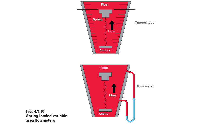
However, another important feature is also revealed: if the pass area (the area between the float and the tube) increases at an appropriate rate, then the differential pressure across the spring loaded variable area flowmeter can be directly proportional to flow.
To recap a few earlier statements
With orifice plates flowmeters:
- As the rate of flow increases, so does the differential pressure.
- By measuring this pressure difference it is possible to calculate the flowrate through the flowmeter.
- The pass area (for example, the size of the hole in the orifice plate) remains constant.
With any type of variable area flowmeter:
- The differential pressure remains almost constant as the flowrate varies.
- Flowrate is determine from the position of the float.
- The pass area (the area between the float and the tube) through which the flow passes increases with increasing flow.
Figure 4.3.11 compares these two principles.
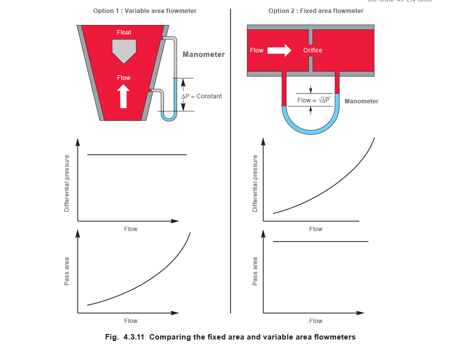
The spring loaded variable area principle is a hybrid between these two devices, and either:
- The displacement of the float - Option 1
or
- The differential pressure - Option 2
...may be used to determine the flowrate through the flowmeter.
In Option 1 (determining the displacement of the float or ‘flap’). This can be developed for steam systems by:
- Using a torsion spring to give a better operating range.
- Using a system of coils to accurately determine the angle of the ‘flap’ that is displaced when the steam is flowing through the flowmeter.

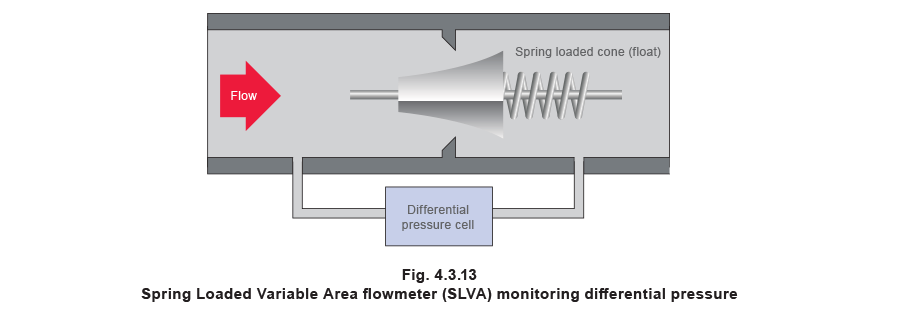
In Option 2 (Figure 4.3.13), namely, determining the differential pressure, this concept can be developed further by shaping of the float to give a linear relationship between differential pressure and flowrate. See Figure 4.3.13 for an example of a spring loaded variable area flowmeter measuring differential pressure. The float is referred to as a cone due to its shape.
Advantages of a spring loaded variable area (SLVA) flowmeter:
- High turndown, up to 100:1.
- Good accuracy ±1% of reading for pipeline unit.
- Compact – a DN100 wafer unit requires only 60 mm between flanges.
- Suitable for many fluids.
Disadvantages of a variable area spring load flowmeter:
- Can be expensive due to the required accessories, such as the DP cell and flow computer.
Typical applications for a variable area spring load flowmeter:
- Boiler house flowmetering.
- Flowmetering of large plants.
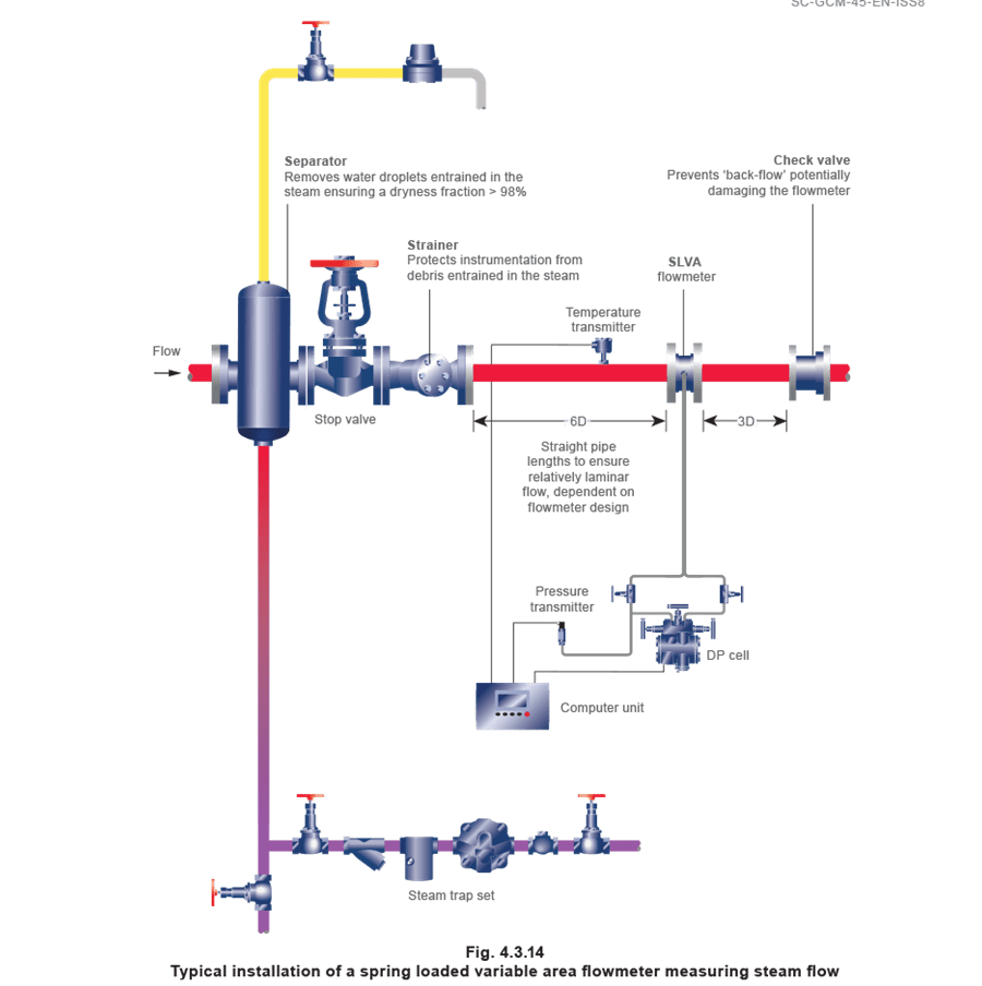
To ensure that a flowmeter achieves its optimal performance, correct installation is essential.
Figure 4.3.14 illustrates a typical steam flowmetering station using a SLVA flowmeter and identifies the other recommended component parts that are required for optimal performance. It is worth noting that each application is different and that other flowmeters may require alternative component parts to those illustrated in Figure 4.3.14.
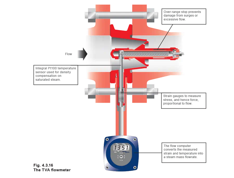
Target Variable Area (TVA) flowmeter
The TVA flowmeter operates on the well established spring loaded variable area (SLVA) principle, where the area of an annular orifice is continuously varied by a precision shaped moving cone.
This cone is free to move axially against the resistance of a spring.
However, unlike other SLVA flowmeters, the TVA does not rely on the measurement of differential pressure drop across the flowmeter to calculate flow, measuring instead the force caused by the deflection of the cone via a series of extremely high quality strain gauges. The higher the flow of steam the greater the force. This removes the need for expensive differential pressure transmitters, reducing installation costs and potential problems (Figure 4.3.15).
The TVA has an internal temperature sensor, which provides full density compensation for saturated steam applications.
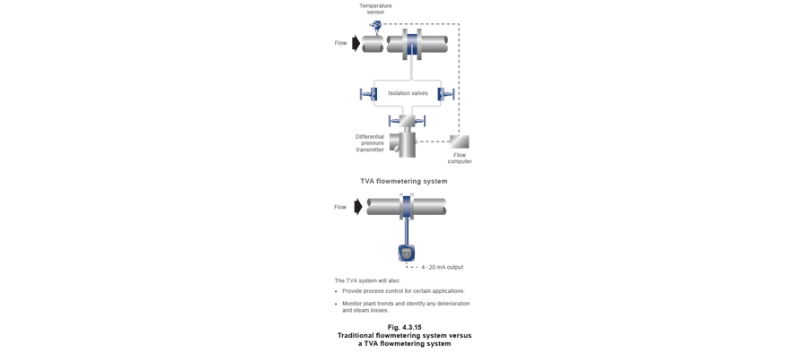
The TVA steam flowmeter (Figure 4.3.15) has a system uncertainty (accuracy) in accordance with EN ISO / IEC 17025, of:
• ±2% of actual flow to a confidence of 95% over a range of 10% to 100% of maximum rated flow.
• ±0.2% FSD to a confidence of 95% from 2% to 10% of the maximum rated flow.
As the TVA is a self-contained unit the uncertainty quoted is for the complete system. Many flowmeters claim a pipeline unit uncertainty but, for the whole system, the individual uncertainty values of any associated equipment, such as DP cells, need to be taken into account.
The turndown of a flowmeter is the ratio of the maximum to minimum flowrate over which it will meet its specified performance, or its operational range. The TVA flowmeter has a high turndown ratio of up to 50:1, giving an operational range of up to 98% of its maximum flow.
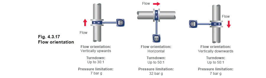
Flow orientations
The orientation of the TVA flowmeter can have an effect on the operating performance. Installed in horizontal pipe, the TVA has a steam pressure limit of 32 bar g, and a 50:1 turndown. As shown in Figure 4.3.17, if the TVA is installed with a vertical flow direction then the pressure limit is reduced due to the loss of the water seal protecting the electronics from the steam temperature.
In addition, the turndown ratio will be reduced if the flow is vertically upward. This is because the weight of the cone causes it to sit against the orifice at lower flows. Once the cone is at that point the sensor cannot accurately detect any further reduction in flow.
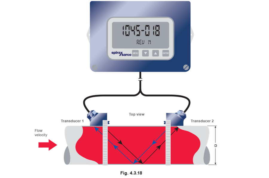
Ultrasonic flowmeters
The principle of operation for a ‘transit-time’ ultrasonic flowmeter is based on measuring the time it takes for ultrasound pulses to pass between two transducers attached to the pipe of the fluid being monitored. (Figure 4.3.18). Each transducer alternatively fires pulses of ultrasound where the time it takes for each pulse to reach the other transducer is affected by the velocity of the fluid flowing through the pipe. By knowing this information, flow velocity can be calculated, leading to the volumetric and mass flowrates of the fluid being monitored. This is covered in more detail in Module 4.2 – Principles of Flowmetering.
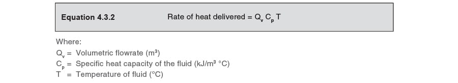
A typical application for ultrasonic flowmeters is energy monitoring, where Resistant Temperature Detectors (RTD’s) form part of the transducers’ assembly. The RTD’s measure the temperature of the flowing liquid, allowing the rate of energy flowing through the pipe to be calculated, using the equation below:
One of the greatest benefits of an ultrasonic flowmeter is that the transducers or RTD’s are externally mounted. This means that there is no invasive installation requiring pipeline genetration or pipeline shutdowns. In addition, with no moving parts or components in the flow being measured, there are no issues concerning corrosion and erosion, so minimising maintenance requirements. Any maintenance that is required can be carried out without the need to shutdown the pipeline.
Ultrasonic flowmeters are best suited to monitoring liquids, such as measuring condensate return. The fluid passing through the pipe being measured must be single phase, in other words, the line must be flooded. Ultrasonic flowmeters cannot accurately measure a mixture of water and steam or air, for example.
Advantages of ultrasonic flowmeters:
- Quick and simple installation, requiring no plant downtime, as all components are externally mounted.
- Bidirectional flow measurement.
- Highly accurate (up to 1% of flowrate).
- Can be used to measure energy flow.
- Fluid conductivity not an issue.
- Corrosive fluids not an issue.
- A turndown of 30:1 is achievable with the correct installation.
- Cost of unit is independent of pipeline size, making it commercially attractive for larger pipelines.
Disadvantages of ultrasonic flowmeters:
- For single phase liquids only.
- 10-30D straight pipeline lengths required.
- Not as accurate as in-line flowmeters.
- Unreliable if there is more than 5% gas or vapour in the pipeline.
Typical applications for ultrasonic flowmeters:
- Liquid flowmetering: As with all liquids, care must be taken to remove air and gases prior to them being metered. If the unit is used for condensate flowmetering it is important that the line is flooded and no live or flash steam is present.
- Energy monitoring for heating and cooling applications.
Every ultrasonic flowmeter operates within minimum and maximum signal strengths to provide accurate measurement readings. If the signal strength is too weak the flowmeter will not detect flow and if the signal strength goes beyond the maximum signal strength specified the pipeline will become ‘flooded’ and the signal received will result in inaccurate flow measurement. For optimum results the signal strength should be in the range specified by the manufacture.
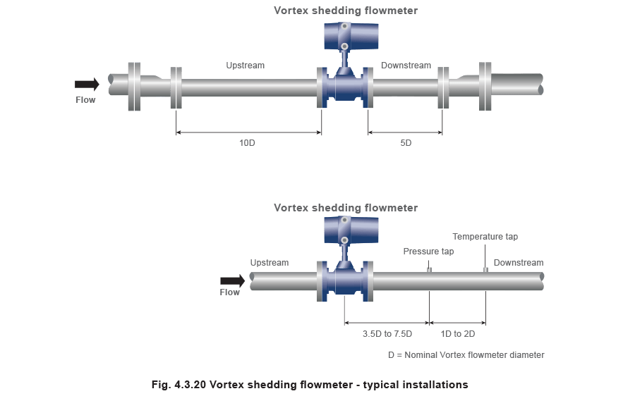
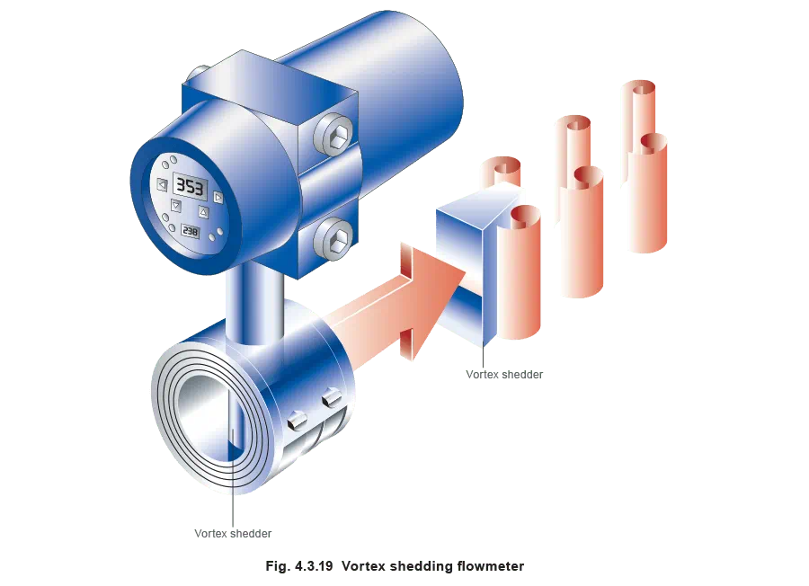
Vortex shedding flowmeters
These flowmeters utilise the fact that when a non-streamlined or ‘bluff’ body is placed in a fluid flow, regular vortices are shed from the rear of the body. These vortices can be detected, counted and displayed. Over a range of flows, the rate of vortex shedding is proportional to the flowrate, and this allows the velocity to be measured.
The bluff body causes a blockage around which the fluid has to flow. By forcing the fluid to flow around it, the body induces a change in the fluid direction and thus velocity. The fluid which is nearest to the body experiences friction from the body surface and slows down. Because of the area reduction between the bluff body and the pipe diameter, the fluid further away from the body is forced to accelerate to pass the necessary volume of fluid through the reduced space. Once the fluid has passed the bluff body, it strives to fill the space produced behind it, which in turn causes a rotational motion in the fluid creating a spinning vortex.
The fluid velocity produced by the restriction is not constant on both sides of the bluff body. As the velocity increases on one side it decreases on the other. This also applies to the pressure.
On the high velocity side the pressure is low, and on the low velocity side the pressure is high.
As pressure attempts to redistribute itself, the high pressure region moving towards the low pressure region, the pressure regions change places and vortices of different strengths are produced on alternate sides of the body.
The shedding frequency and the fluid velocity have a near-linear relationship when the correct conditions are met.
The frequency of shedding is proportional to the Strouhal number (Sr), the flow velocity, and the inverse of the bluff body diameter. These factors are summarised in Equation 4.3.3.
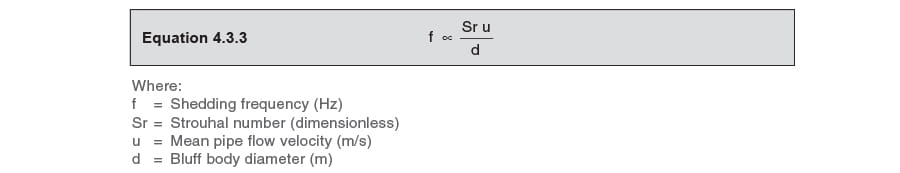
The Strouhal number is determined experimentally and generally remains constant for a wide range of Reynolds numbers;which indicates that the shedding frequency will remain unaffected by a change in fluid density, and that it is directly proportional to the velocity for any given bluff body diameter. For example:

Then the volume flowrate qv in a pipeline can be calculated as shown in Equation 4.3.4:

Advantages of vortex shedding flowmeters:
- Reasonable turndown (providing high velocities and high pressure drops are acceptable)
- No moving parts.
- Little resistance to flow.
Disadvantages of vortex shedding flowmeters:
- At low flows, pulses are not generated and the flowmeter can read low or even zero.
- Maximum flowrates are often quoted at velocities of 80 or 100 m/s, which would give severe problems in steam systems, especially if the steam is wet and/or dirty. Lower velocities found in steam pipes will reduce the capacity of vortex flowmeters.
- Vibration can cause errors in accuracy.
- Correct installation is critical as a protruding gasket or weld beads can cause vortices to form, leading to inaccuracy.
- Long, clear lengths of upstream pipework must be provided, as for orifice plate flowmeters.
Typical applications for vortex shedding flowmeters:
- Direct steam measurements at both boiler and point of use locations.
- Natural gas measurements for boiler fuel flow.