Pipeline ancillaries

Contents
Isolation Valves - Linear Movement
Isolation valves are used for diverting process media, facilitating maintenance, equipment removal and shutdown. The operation, application and construction of gate, globe, piston and diaphragm valves are studied in this tutorial.
Isolation Valves - Linear Movement
Isolation valves are a key component in any fluid system as they are used to stop the flow of fluid into a particular area of the system. They are also sometimes used to manually control the flow of the fluid. The European standard EN 736-1:1995 distinguishes between isolating, regulating and control valves as follows:
- Isolating valve - A valve intended for use only in the closed or fully open position.
- Regulating valve - A valve intended for use in any position between closed and fully open.
- Control valve - A power-operated device which changes the fluid flowrate in a process control system.
Isolation valves are used in a wide variety of different applications where on/off type control is required, these include:
- Diverting process media.
- Flow isolation to:
- Facilitate maintenance
- Allow the removal of equipment
- Allow the shut down of plant
A multitude of different types and designs of isolation valve have been developed in order to meet this range of applications and the diverse operating conditions in which they are used.
Valves are commonly classified into two groups (see Table 12.1.1), according to the operating motion of the closure device (or obturator):
- Linear movement valves - The obturator moves in a straight line. Included in this category are gate valves, globe valves, diaphragm valves and pinch valves. These valves are covered in greater depth within this module.
- Rotary movement valves - The obturator rotates about an axis at right angles to the direction of flow. Ball valves and butterfly valves are the two most important rotary valves associated with steam applications and are covered in greater depth in Module 12.2, Isolation Valves - Rotary Movement.
| Valve moment | Linear | Rotary | ||
| Operating motion of the closing device (obturator) | Straight line | Rotating about an axis at right angles to the direction of flow | ||
| Direction of flow in the seating area | At right angles to the operating motion of the obturator |
Longitudinal to the operating motion of the obturator |
Through the obturator | Around the obturator |
| Basic types | Gate valve | Globe valve | Ball valves | Butterfly valve |
| Schematic |  |
 |
 |
 |
Linear movement valves
Linear movement valves have been developed from the early forms of sluice gates used to control the flow of water in irrigation channels. Since then, a large number of different designs and types have been developed for use in almost every type of flow application. Although linear movement valves are characterised by straight-line obturator movement, the flow of the fluid may be at right angles to this movement (as in the case of gate valves), or in the same direction, as with globe valves. The main feature of the linear movement valve is that tight shut-off may be achieved by tightening down the obturator on a threaded stem.
Gate valves
Gate valves are probably the most common valves in use today due to their widespread use in domestic water systems, but it should be noted that their popularity in industry has declined in recent years. However, they are still used where an uninterrupted flow is required, because the gate fully retracts into the bonnet, creating a minimal pressure drop, when the valve is in an open position. Gate valves are specifically intended for use in isolation applications.
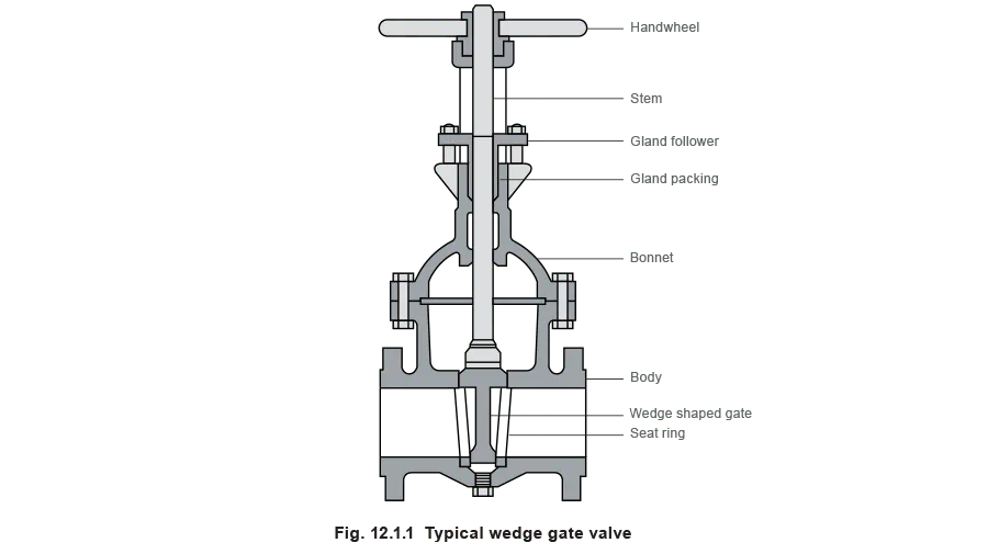
A gate valve consists of four main components, the body, bonnet (or cover), gate and stem. A typical gate valve is shown in Figure 12.1.1.
The gate, which slides between the seats, is lifted in a direction at right angles to the flow until clear of the flow path. The fact that the gate fully retracts into the bonnet ensures that the pressure drop across the valve is low.
Gate valves are divided into a number of different classes, depending on the design of the gate and its seating faces.
Solid wedge gate valve
The gate is wedge shaped and it seats on corresponding faces in the valve body. The mechanical advantage of the activating thread, together with the wedge angle, enables adequate seating forces to be applied against the fluid pressure without excessive handwheel effort. The seat can sometimes be coated with PTFE to assist a high integrity shut-off. A typical solid wedge gate valve is shown in Figure 12.1.1.
Flexible wedge gate vale
Although there are several types of flexible wedge gate valves, they all make use of a flexible two-part disc, which is shaped like two wheels on a very short axle. The flexibility of the disc ensures tight seating over a wide range of temperatures and pressures.
The most common type of flexible wedge gate valve used in steam applications is the parallel slide valve. The two plates that constitute the gate are held against the seat by a spring, encased between them. The fluid pressure moves the upstream disc off its seat, and the force is transferred onto the downstream disc, thereby ensuring a tight shut-off. The high degree of flexibility in the gate allows for expansion and contraction when subjected to temperature variations, making it suitable for use in steam systems.
Globe valves
Globe valves constitute a major class of linear movement valves; they have become more popular than gate valves as there is a wide variety of configurations available to suit most applications. The movement of fluid through the valve seat is longitudinal to the operating motion of the obturator; this means that for a valve in which the inlet and outlet are horizontally opposed, the fluid must follow a changing course. The main advantage of this arrangement is that a globe valve opens more rapidly than a gate valve as the disc only needs to move a small distance from its seat to allow full flow. This is an advantage when there is frequent operation of the valve. The disadvantage is that the fluid has to change course, increasing the resistance to flow and generating turbulence. This results in a higher pressure drop across a globe valve than a gate valve.
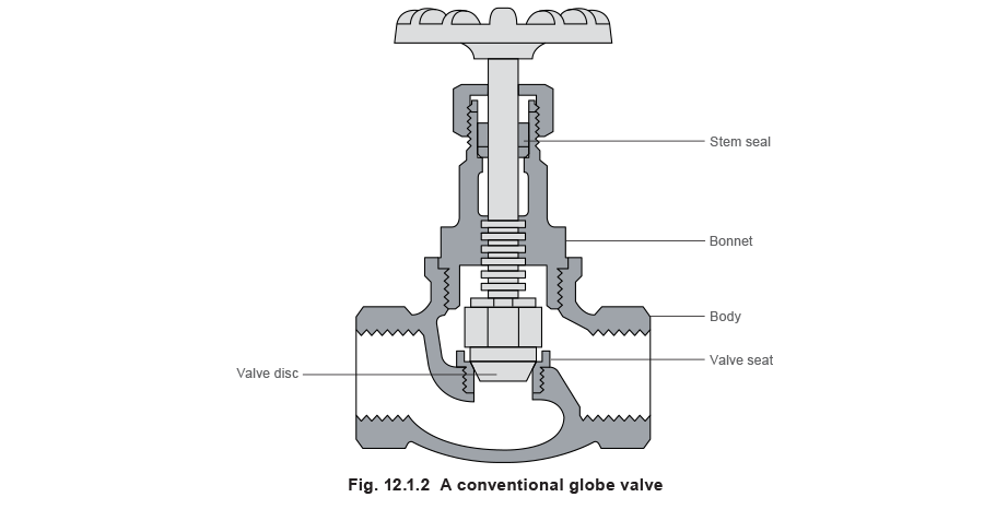
Globe valves are less likely to leak than gate valves, which means that they can be used for higher pressure or higher volume applications, for example in steam systems, or where fluid loss can be hazardous or costly. The increased cost of globe valves over gate valves is therefore offset by the additional safety they provide, and a reduced chance of fluid loss.
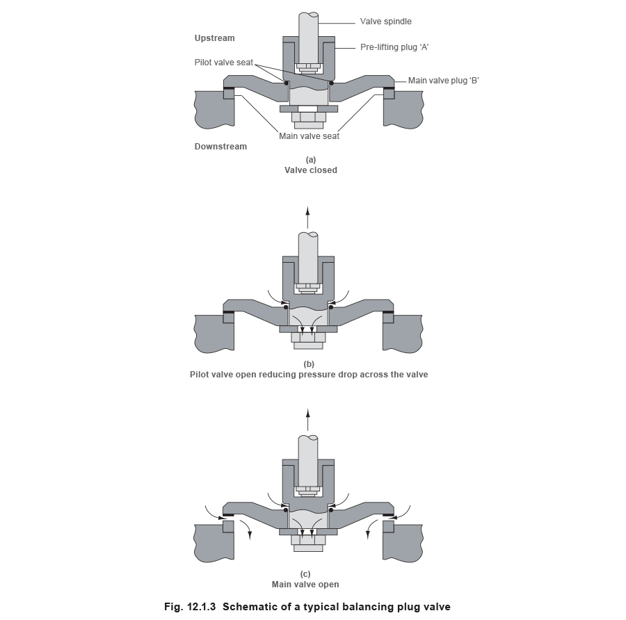
The pressure of the fluid acting over the area of the disc generates an axial load on the stem. This makes closing the valve difficult, so much so, that it limits the size of a standard globe valve to DN250. On high differential pressure closed systems, balancing plugs can be used to overcome this effect, allowing valves with a nominal diameter of up to 500 mm to be used (Figure 12.1.3(a)). The balancing plug contains a pre-lifting plug that acts as a pilot valve. When the valve is opened, the pre-lifting plug opens first, allowing the medium to pass through it at a controlled rate (Figure 12.1.3(b)). This reduces the differential pressure across the valve, enabling the disc to be easily lifted off its seat (Figure 12.1.3(c)). To assist closing of the valve, isolation valves fitted with a balancing plug have to be fitted in reverse so that the top of the plug is acted on by the upstream pressure.
Piston valves
One of the main disadvantages of linear movement valves is the fact that their seats are prone to damage from dirt and wiredrawing, and therefore, depending on the application may require regular maintenance. Although these seats are replaceable in theory, it usually involves significant time and cost, and it is often more advantageous to replace the entire valve. To overcome this problem, piston valves have been developed.
The piston valve is a variant of the conventional globe valve, with the traditional seat and cone replaced by a piston and lantern bush. The piston is connected to the valve stem and handwheel, and passes through two sealing rings that are separated by a lantern bush. When assembled, the two sets of sealing rings are compressed around the piston by the load exerted along the stem. The upper set of sealing rings acts as conventional gland packing, and the lower set acts as the seat. Furthermore, the large sealing area between the piston and rings assures a high level of shut-off tightness.
The piston valve is not designed for throttling duties and must be used in the fully open or closed positions. When the valve is fully opened, only the bottom face of the piston is exposed to the fluid as the rest of the body is protected by the upper sealing rings. This means that the sealing surfaces (the sides of the piston) are protected from erosion by the fluid flow.

If the valve requires maintenance, all the internals can be easily removed by undoing the cover nuts and withdrawing the piston. The rings and the lantern bush can then be removed using an extractor tool. This operation is simple and can be undertaken without having to remove the valve from the pipeline. In general, the piston should never have to be replaced, but the sealing rings may wear over a long period with frequent operation.
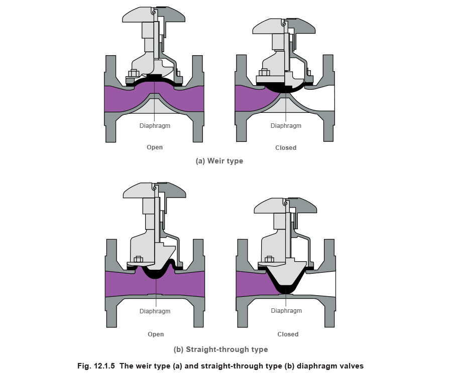
Diaphragm valves
Diaphragm valves constitute the third major type of linear movement valves. The stem of the valve is used to push down a flexible diaphragm, which in turn blocks the path of the fluid. There are two different classifications of diaphragm valve based on the geometry of the valve body:
- Weir type - A weir is cast into the body, and when closed, the diaphragm rests on the weir, restricting the flow (see Figure 12.1.5 (a)).
- Straight-through type - The bore runs laterally through the body and a wedge shaped diaphragm is used to make the closure (see Figure 12.1.5 (b)).
The main advantage of a diaphragm valve is the fact that the diaphragm isolates the moving parts of the valve from the process fluid. They are therefore suitable for handling aggressive fluids and for those containing suspended solids. In addition, as the bonnet assembly is not exposed to the fluid, it can be made from inexpensive materials such as cast iron, thereby reducing the overall cost. The development of new diaphragm materials enables diaphragms to be used on most fluids. Their application is however limited by the temperature that the diaphragm can withstand - typically less than 175°C. Diaphragm valves are generally used on process fluid applications.
Linear movement valve stem options
Linear movement valves are available with a number of different stem arrangements:
- Rising /non-rising stems - If the stem is rising, it will move vertically upwards when the valve is opened, as opposed to only rotating, as with a non-rising stem. The rising stem indicates the degreee of valve opening, which in turn roughly reflects the amount of flow through the valve. Valves with rising stems do however require more space above the bonnet to accommodate the stem in the fully open position. The use of non-rising stems is recommended on gland packed valves, as they reduce the wear on the packing.

- Inside/outside stem screws - On a stem with an outside screw, the actuating threads on the stem are situated outside the valve body and are not exposed to the process fluid. As screw threads are particularly susceptible to corrosion, outside screws should always be used onfluids with corrosive or erosive properties. They are also beneficial where the valve is frequently exposed to large temperature variations, as the expansion and contraction of the stem may cause binding of the threads inside the body.

Stem sealing
In order to prevent leakage of the process media from around the stem of a valve, a barrier must be placed between the fluid and the environment. Stem sealing is usually achieved by one of two methods, namely gland packing and bellows sealing. Gland packing consists of a polymeric material, typically PTFE, packed tightly between the stem and the bonnet of the valve, thereby preventing any process media escaping.

In bellows sealed valves, a flexible metallic bellows is used. It is connected on one end to the stem and the other end is connected to the bonnet, effectively producing a barrier between the fluid and the environment. This bellows extends and contracts as the stem moves up and down. The bellows is so effective, it produces a ‘zero emissions’ seal. Fitted to the bellows is an anti-torsion device, which prevents the bellows from rotating with the stem. Such a device is essential, otherwise the repeated twisting of the bellows would lead to the failure of the seal.
Although less costly than the bellows sealed valves, the gland packed valve does not produce such a tight seal as the bellows. If a gland packed valve is not used for a significant period, the gland packing can stiffen, and leakage will occur the next time the valve is used. The bellows sealed valve does not suffer from this problem. Furthermore, gland packed valves require regular re-packing of the gland, whereas a typical bellows requires no maintenance for over 10,000 cycles.