Pipeline ancillaries

Contents
Isolation Valves - Rotary Movement
Isolation valves are used for diverting process media, facilitating maintenance, equipment removal and shutdown. The operation, application and construction of rotary movement (quarter turn) valves, including ball valves and butterfly valves, are covered in this tutorial.
Rotary movement valves, often called quarter-turn valves, include ball valves and butterfly valves. Regardless of the type of rotary movement valve, the obturator rotates about an axis perpendicular to the direction of flow. Fluid may flow through the obturator, as is the case with ball valves, or around it, as with butterfly valves. Rotary movement valves tend to have a simple operating mechanism and are therefore easy to automate and maintain.
Ball valves
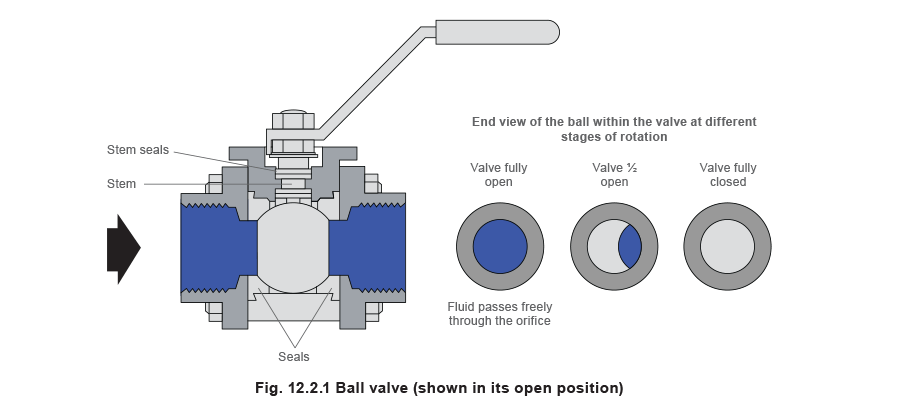
Ball valves were developed during World War II and were initially intended for use in aircraft fuel systems, where weight and space are at a premium. They consist of a body which houses a rotating ball which has an orifice or bore machined directly through it. The ball is located in the body by two sealing rings.
Rotation of the ball through 90° opens and closes the valve and allows fluid to flow directly through the orifice. In the closed position, the blank sides of the ball block the inlet and the outlet preventing any flow. There are two basic designs of ball valves – the floating ball design, which relies on the valve seats to support the ball, and the trunnion mounted ball, which uses a trunnion to support the ball. Trunnion mounting is used on larger valves, as it can reduce the operating torque to about two-thirds of that provided by a floating ball.
Conventionally, the handle that is attached to the ball is in-line with the axis of the pipe when the valve is open; conversely, if it is at right angles to the pipe axis, this indicates that the valve is closed.
Ball valves are available as reduced bore or full bore. Full bore valves have an orifice that is the same size as the diameter of the pipe, whereas in reduced bore valves, the orifice diameter is less than that of the pipe. Full bore valves cost more than reduced bore valves, and they should be used where the pressure drop across the valve is critical or where ball valves are used upstream of flowmeters.
Full bore valves can be used in flowmeter applications to minimise fluid turbulence upstream of the measuring device.
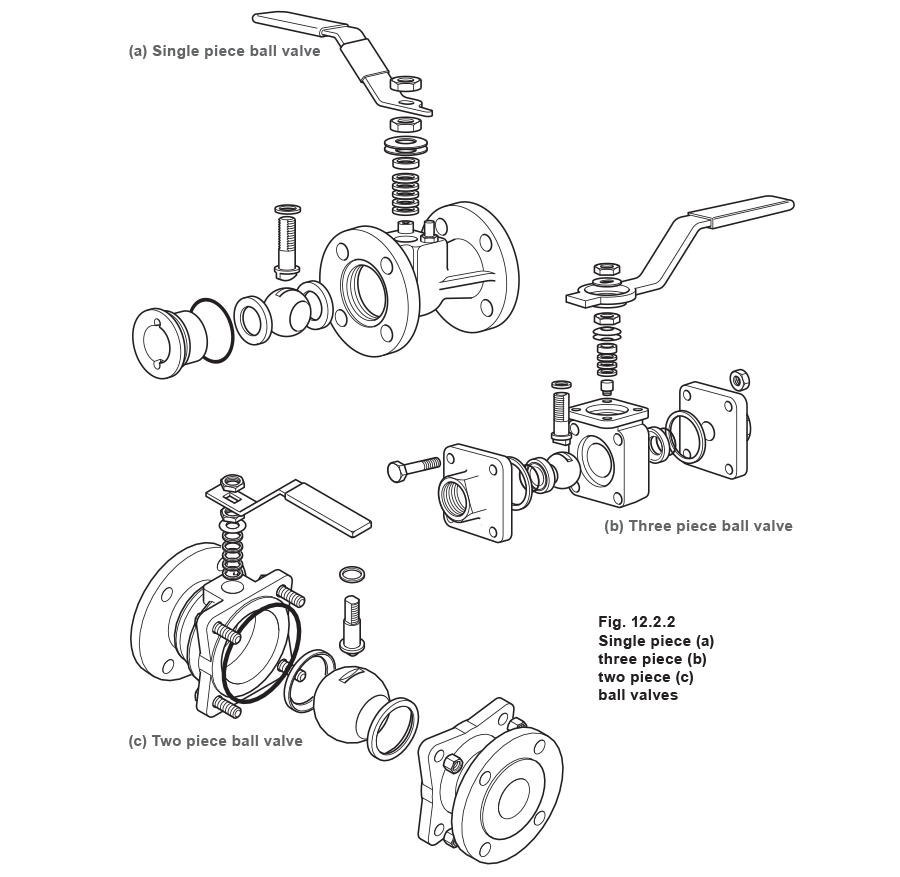
In order to insert the ball into the body, three different types of assembly exist. Not only does the type affect the ease of assembly, but it also influences the maintainability of the valve.
- Two and three piece valves - The body of the valve is split in one or two places in the same plane as the valve flange, and these pieces are bolted together. This has the advantage of simplified, in-line maintenance.
- Top entry valves - The ball is inserted through a bonnet in the top of the valve. This facilitates in-line maintenance.
- Single piece valves - The ball is enclosed in the body by an insert fitted along the valve’s axis. This eliminates the possibility of body joint leakage and any chance of disconnection whilst in service, but when maintenance is required, the whole valve has to be removed from the pipeline.
The choice of seat material determines the conditions for which a particular ball valve is most suited. Although new seat materials are continually being developed, Table 12.2.1 lists some of the more common materials in use today.
Table 12.2.1 Common ball valve seat materials
| Application | Seat material | Maximum operating temperature |
| Low temperatures | PTFE | 200 °C |
| Carbon reinforced PTFE | 230 °C | |
| High pressures | Polyetheretherketone (PEEK) | 250 °C |
| High temperatures | Metal | 1 000 °C |
Ball valve options
Ball valves can be produced with a number of options to meet the demands of a wide variety of applications:
- Actuators - Ball valves, and indeed all rotary valves, are suitable for automation. This is usually accomplished by using either an electrically or pneumatically operated actuator. The actuator is connected to the valve through a linkage kit. Although not essential, an ISO standard mounting pad enables the linkage kit to be installed without dismantling the valve, which maintains valve integrity. Refer to Module 6.6 for more information on actuators.
- Firesafe - As ball valves are commonly used in gas and oil pipelines, it is essential that the valves used in such applications are firesafe. A valve is considered firesafe if, when exposed to fire conditions, it will continue to provide minimal leakage through the seat and stem, and provide effective shut-off during or following a fire or exposure to excessive temperatures. Standards relating to fire-safety are set out in BS 6755 and API RP 6FA.
The main concern is that burning temperatures will destroy soft seats and seals; a number of methods have been developed to overcome this. One approach is to include secondary metal sealing surfaces behind the polymeric seats as an integral part of the body. When exposed to burning temperatures, the seat begins to deform and the pressure of the process media displaces the ball so that it extrudes the polymeric seat (Figure 12.2.3(b)). When the seat has been completely destroyed, the ball will seat against the body metal sealing surface, providing a tight shut-off (Figure 12.2.3(c)).

In addition to the inherent safety of the seating mechanism, the stem seal must also be capable of preventing leakage to atmosphere under ‘fire’ conditions. This can be achieved by using high temperature seals made from flexible graphite or Grafoil®; alternatively, a bellows sealed arrangement can be used (see Figure 12.2.4).

- Clean steam valves - A number of applications exist that require the valve to be of a ‘clean’ design; these include steam applications where there is direct injection of steam into the product and process fluid lines in the biotechnology, food and electronics industries. The main area of concern in such applications is the space between the body and the ball; process fluid may accumulate in these spaces leading to contamination and corrosion. This can be overcome by inserting cavity fillers in these spaces. The cavity filler may be an integral part of the seat or a separate component in the valve assembly. Furthermore, ball valves used in clean steam applications should be made from stainless steel with a good surface finish (less than 81 microns Ra is recommended).
- Throttling applications - When ball valves are used in throttling applications, high velocity flow can impinge against a localised area of the ball and seals, causing premature deterioration of the seating material. Modifications to the standard design are required for ball valves to be used for throttling; these include the use of metal seats, hard coatings and, sometimes, modifications to the ball, to give a characterised flow pattern.
Butterfly valves
Although there are many different designs of butterfly valve, they all consist of a disc that rotates on a shaft at right angles to the fluid flow. When open, the disc is edge-on to the flow and the fluid passes around it, offering limited resistance. In the closed position, the disc is rotated against a seat in the body of the valve.
Butterfly valves usually take up little more room than a pair of pipe flanges, and are therefore an attractive alternative to the ball valve where space is limited. In fact, some butterfly valves are designed specifically for insertion between pipe flanges, these are known as wafer butterfly valves.

The main disadvantage of butterfly valves is that the shut-off is not as tight as that achieved by other valve types. This can be alleviated to an extent by offsetting the axis of rotation of the discand using pressure assisted seats. By using an offset axis of rotation, a ‘camming’ action is generated, which means that the disc creates a tight seal with the seat during the last few degrees of shut-off. These high performance or eccentric-type butterfly valves have improved shut-off capabilities and their design enables them to be used for throttling.
For steam applications, butterfly valves have largely been superseded by ball valves. Butterfly valves are more commonly used in liquid systems or where space is limited. The compactness of butterfly valves means less material is required and they are therefore ideal where the application specifies the use of costly materials, for example, in seawater applications where nickel is specified.
Selection and sizing of isolation valves
A process fluid must be fully contained in a properly designed piping system to avoid endangering personnel and the environment, and contamination of the fluid itself. The pipeline system can have many potential leak paths, such as pipe joints, seams, equipment connections and, most importantly, valves. Valves can be one of the biggest contributors to plant problems if they are wrongly selected or are poorly designed or manufactured. Furthermore, a valve, when selected correctly for the application should last at least the life of the plant, if maintained properly.
When selecting an isolating valve for a particular application, a number of factors need to be considered; these are shown in Table 12.2.2, along with the valve selection parameter that is affected.
Table 12.2.2 Factors affecting the selection of an isolation valve
| Factors affecting the selection of an isolation valve | Areas of concern | Affected parameter |
| Process medium | Fluid – liquid or gas Pressure Temperature Flowrate Corrosive Abrasion |
Type of valve Material of construction Maintainability Valve size |
| Functional requirements | Speed of operation Fails - safe Frequency of operation Emission loss to atmosphere |
Type of valve |
| Method of operation | Manual Pneumatic Electric Electropneumatic Hydraulic |
Type of valve Type of actuator |
| Pipeline | Pipeline material Pipeline size Pipeline loss |
Valve size End connections Type of valve Material of construction Availability |
| Special Requirements | Firesafe Free draining Antistatic |
Cost Type of valve |
Table 12.2.3 summarises the main characteristics of the different types of isolation valve.
Table 12.2.3 Typical sizes and operating ranges of isolation valves
| Valve type | Size | Pressure range | Temperature range | Pressure drop | |||
| Minimum (mm) | Maximum (mm) | Minimum (bar) | Maximum (bar) | Minimum (⁰C) | Maximum (⁰C) | Bar | |
| Gate | 3 | 2250 | >0 | 700 | -196 | 675 | 0.007 |
| Globe | 3 | 760 | >0 | 700 | -196 | 650 | 0.590 |
| Diaphragm | 3 | 610 | >0 | 21 | -50 | 175 | 0.021 |
| Ball (full bore) | 6 | 1220 | >0 | 525 | -55 | 300 | 0.007 |
| Butterfly | 50 | 1830 | >0 | 102 | -30 | 538 | 0.120 |
1 Note: Typical values for a DN150 bore valve passing saturated steam at 24 bar, flowing at 40 m/ s.
Table 12.2.4 summarises the applications of the most common isolating valve types in use today.
Table 12.2.4 Applications of isolating valve types
| Valve Type | General Applications | Actuation | Remarks |
| Globe valve | Shut-off/regulation of liquid/gas flow. Steam and condensate applications |
Usually manual, but may be: - Electric - Manual - Hydraulic - Pneumatic |
Usually applied to higher pressure or high volume systems, due to cost. Less sustainable for viscous or contaminated fluids. |
| Piston valve | Used fully open or fully closed for on/off regulation on steam, gas and other fluid services. Typically used on fluids that cause excessive seat water. |
Usually manual, but may be: - Electric - Manual - Hydraulic |
Usually used where the valve body is to be permanently installed and maintenance needs to be minimised. |
| Gate valve | Normally used fully open or fully closed for on/off regulation on water, oil, gas, steam and other fluid services. | Usually manual, but may be: - Electric - Manual - Hydraulic |
Not recommended as a throttling valve. Solid wedge gate is free from chatter and jamming. Parallel slide valve used in steam systems. |
| Butterfly valve | Shut-off and regulation in larger pipelines in waterworks, process industries, HPI, power generation. | Handwheel Electric motor Pneumatic actuator Hydraulic actuator Air motor |
Relatively simple construction. Can be produced in very large sizes. Eccentric design essential for steam systems. Typically used on liquid systems. |
| Ball valve | Wide range of applications in all sizes, including HPI. Steam and condensate applications. |
Handwheel Electric motor Pneumatic actuator Hydraulic actuator |
Can handle all fluid types. Limited maximum pressure. |
Table 12.2.5 is a generalised guide to the selection of isolation valves for particular steam and condensate applications. It should be noted that the choice of isolation valve is subjective and different industries and those in different geographical regions have their own unique preferences.
Table 12.2.5 Selection of valves for steam/condensate isolation purposes
Note: in this table, bellows sealed refers to a bellows sealed globe valve and globe refers to a standard, gland packed globe valve.
| Application | Choice | Standard application | Dead tight shut-off | Energy and maintenance savings | Zero emissions |
| Trap sets up to 100 mm | 1st | < DN50 Ball > DN50 Globe |
< DN25 Piston > DN25 Ball |
< DN25 Piston > DN25 Ball |
Bellows sealed globe |
| 2nd | < DN50 Ball > DN50 Bellows sealed |
Bellows sealed | Bellows sealed | < DN25 Piston > DN25 Ball |
|
| Mains and equipment < 50 mm | 1st | Globe | Ball | Piston | Bellows sealed |
| 2nd | Ball | Piston | Bellows sealed | Piston | |
| Mains and equipment 50 mm - 100 mm | 1st | Bellows sealed | Bellows sealed | Bellows sealed | Bellows sealed |
| 2nd | Globe | Ball | Ball | Ball | |
| Mains and equipment > 100 mm | 1st | Bellows sealed | Bellows sealed | Bellows sealed | Bellows sealed |
| 2nd | Globe | Globe | Globe | Globe | |
| Automated mains and equipment | 1st | Bellows sealed | Bellows sealed | Bellows sealed | Bellows sealed |
| 2nd | Globe | Ball | Ball | Ball |
Once the most suitable type of valve has been chosen, it is necessary to choose the correct size. Valves are typically sized according to the pipeline size. It is however advisable to check that the pressure drop across the valve (when it is fully open) is within acceptable limits. The pressure drop is a function of the valve flow coefficient (or Kvs value), the flowrate and the inlet pressure. Specification sheets usually contain data about the Kvs value when the valve is fully opened.
With knowledge of the typical operating pressure, and the mass flowrate, it is possible to determine the pressure drop across a chosen valve. Alternatively, if the maximum acceptable pressure drop is known, it is possible to select a suitable valve size. Although there are many formulae and charts available to predict the relationship between flowrate and pressure drop, the following simplified empirical formula (Equation 3.21.1) produces reliable results for steam and is therefore commonly used:

This formula forms the basis of the chart shown in Figure 12.2.7, which was first introduced in Block 3, Module 21.
If the isolating valve is to be used in a liquid system, the pressure drop across the valve is determined using the following equation:


