Steam Engineering Principles and Heat Transfer

Contents
Energy Consumption of Tanks and Vats
The heating of liquids in tanks and vats is an important requirement in process industries. There are many types of tank with different uses. Determination of heat requirements, heat transfer and heat loss calculations are all covered in this tutorial.
The heating of liquids in tanks is an important requirement in process industries such as the dairy, metal treatment and textile industries. Water may need to be heated to provide a hot water utility; alternatively, a liquid may need to be heated as part of the production process itself, whether or not a chemical reaction is involved. Such processes may include boiler feedtanks, wash tanks, evaporators, boiling pans, coppers, calandrias and reboilers.
Tanks are often used for heating processes, of which there are two major categories:
Open and closed tanks are used for a large number of process applications:
Boiler feedtanks
The boiler feedtank is at the heart of any steam generation system. It provides a reservoir of returned condensate and treated make-up water, for feeding the boiler.
One reason for heating the water is to reduce oxygen entering the boiler, with (theoretically) 0 ppm oxygen at 100 °C. Boiler feedtanks are normally operated at between 80 °C and 90 °C.
Hot water tanks
Hot water is required for a number of processes in industry. It is often heated in simple, open or closed tanks which use steam as the heating medium. The operating temperature can be anywhere between 40 °C and 85 °C depending on the application.
Degreasing tanks
Degreasing is the process where deposits of grease and cooling oil are removed from metal surfaces, after machining and prior to the final assembly of the product. In a degreasing tank, the material is dipped into a solution, which is heated by coils to a temperature of between 90 °C and 95 °C.
Metal treatment tanks
Metal treatment tanks, which are sometimes called vats, are used in a number of different processes:
- To remove scale or rust.
- To apply a metallic coating to surfaces.
The treatment temperatures typically range from 70 °C to 85 °C.
Oil storage tanks
Storage tanks are required to hold oils which cannot be pumped at ambient temperatures, such as heavy fuel oil for boilers. At ambient temperatures, heavy oil is very thick and must be heated to 30 °C - 40 °C in order to reduce its viscosity and allow it to be pumped. This means that all heavy oil storage tanks need to be provided with heating to facilitate pumping.
Heating tanks used in process industries
Heating tanks are used by a number of process industries, see Table 2.9.1.
Table 2.9.1 Process industries which use heating tanks
| Industry | Process | Typical temperatures |
| Sugar | Raw juice heating | 80 to 85 °C |
| Dairy | Hot water generation | 80 °C |
| Plating | Metal deposition | 70 to 85 °C |
| Metal/steel | Removal of rust/scale | 90 to 95 °C |
| Pharmaceutical | Wash tanks | 70 °C |
| Rubber | Heating caustic oil | 140 °C |
In some applications the process fluid may have achieved its working temperature, and the only heat requirement may be due to losses from the solid surface of the walls and/or the losses from the liquid surface.
This Module will deal with the calculations which determine the energy requirements of tanks: the following two Modules (2.10 and 2.11) will deal with how this energy may be provided.
When determining the heat requirement of a tank or vat of process fluid, the total heat requirement may consist of some or all of a number of key components:
- The heat required to raise the process fluid temperature from cold to its operating temperature.
- The heat required to raise the vessel material from cold to its operating temperature.
- The heat lost from the solid surface of the vessel to the atmosphere.
- The heat lost from the liquid surface exposed to the atmosphere.
- The heat absorbed by any cold articles dipped into the process fluid.
However, in many applications only some of the above components will be significant. For example, in the case of a totally enclosed well-insulated bulk oil storage tank, the total heat requirement may be made up almost entirely of the heat required to raise the temperature of the fluid.
Items 1 and 2, the energy required to raise the temperature of the liquid and the vessel material, and item 5, the heat absorbed by any cold articles dipped into the process fluid, can be found by using the Equation 2.6.1. Generally, data can be accurately defined, and hence the calculation of the heat requirement is straightforward and precise.

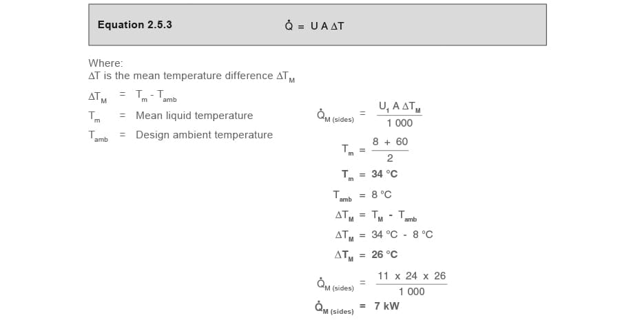
Items 3 and 4, the heat losses from the vessel and liquid surfaces can be determined by using Equation 2.5.3.
However, heat loss calculations are much more complex, and usually empirical data, or tables based on several assumptions have to be relied upon. It follows that heat loss calculations are less accurate.

Heat loss from the solid surface of the vessel to the atmosphere
Heat will only be transferred provided there is a difference in temperature between the surface and the ambient air.
Figure 2.9.1 provides some typical overall heat transfer coefficients for heat transfer from bare steel flat surfaces to ambient air. If the bottom of the tank is not exposed to ambient air, but is positioned flat on the ground, it is usual to consider this component of the heat loss to be negligible, and it may safely be ignored.
- For 25 mm of insulation, the U value should be multiplied by a factor of 0.2
- For 50 mm of insulation, the U value should be multiplied by a factor of 0.1
The overall heat transfer coefficients provided in Figure 2.9.1 are for ‘still air’ conditions only.

Table 2.9.2 shows multiplication factors which need to be applied to these values if an air velocity is being taken into account. However, if the surface is well insulated, the air velocity is not likely to increase the heat loss by more than 10% even in exposed conditions.
Table 2.9.2 Effect on heat transfer with air movement
| Velocity (m/s) | 0 | 1 | 2 | 4 | 6 | 8 | 10 | 12 | 14 | 16 |
| Velocity (km/h) | 0 | 3.6 | 7.2 | 14.4 | 21.6 | 28.8 | 36 | 43.2 | 50.4 | 57.6 |
| Factor X | 1 | 1.4 | 1.7 | 2.4 | 3 | 3.6 | 4.1 | 4.5 | 4.9 | 5.2 |
Velocities of less than 1 m/s can be considered as sheltered conditions, whilst 5 m/s may be thought of as a gentle breeze (about 3 on the Beaufort scale), 10 m/s a fresh breeze (Beaufort 5), and 16 m/s a moderate gale (Beaufort 7).
For bulk oil storage tanks, the overall heat transfer coefficients quoted in Table 2.9.3 may be used.
Table 2.9.3 Overall heat transfer coefficients for oil tanks
| Tank position |
∆T between oil and air |
Overall heat transfer coefficient (W/m2 °C) | |
| Unlagged | Lagged | ||
| Sheltered |
Up to 10 °C | 6.8 | 1.7 |
| Up to 27 °C | 7.4 | 1.8 | |
| Up to 38 °C | 8 | 2 | |
| Exposed |
Up to 10 °C | 8 | 2 |
| Up to 27 °C | 8.5 | 2.1 | |
| Up to 38 °C | 9.1 | 2.3 | |
| Underground | Any temperature | 6.8 | - |
Water tanks: heat loss from the water surface to the atmosphere
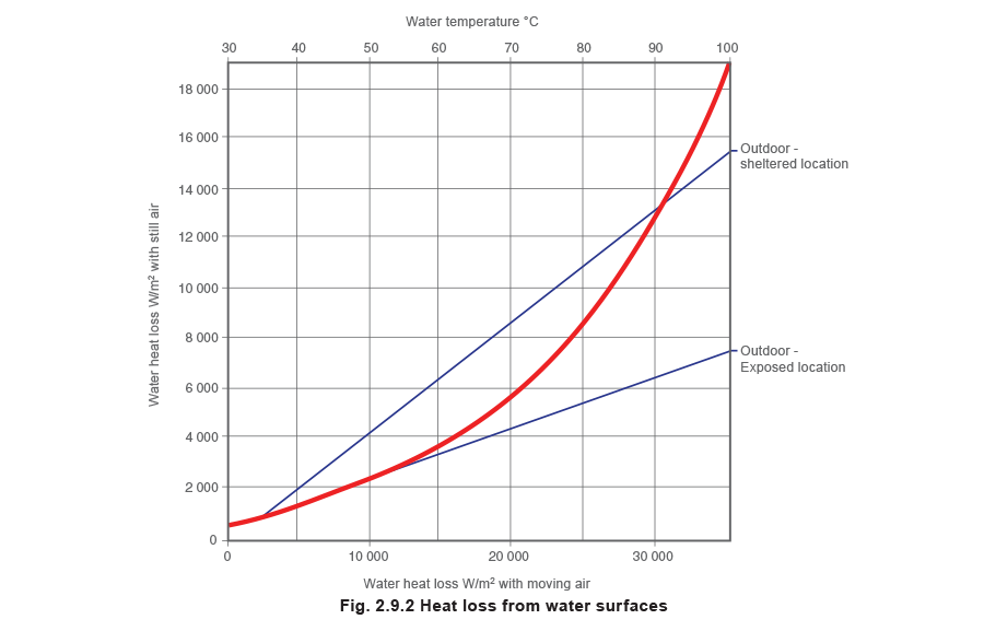
Figure 2.9.2 relates heat loss from a water surface to air velocity and surface temperature. In this chart ‘still’ air is considered to have a velocity of 1 m/s, tanks in sheltered positions outdoors consider velocities at about 4 m/s, whilst tanks in exposed positions outdoors are considered with velocities at about 8 m/s.
This chart provides the heat loss in W/m² rather than the units of the overall heat transfer coefficient of W/m² °C. This means that this value must be multiplied by the surface area to provide a rate of heat transfer, as the water to air temperature difference has already been taken into account.
Heat losses from the water surface, as shown in Figure 2.9.2 are not significantly affected by the humidity of the air. The full range of humidities likely to be encountered in practice is covered by the thickness of the curve. However, the graph considers heat losses with an air temperature of 15.6 °C and 55% air humidity. Different conditions to these can be calculated from the Engineering Support Centre on the Spirax Sarco website.
To determine the heat loss from the chart, the water surface temperature must be selected from the top scale. A line should then be projected vertically downwards to the (bold) heat loss curve.
For indoor tanks a line should be projected horizontally from the intersection to the left-hand scale.
For outdoor tanks a horizontal line should be projected either left or right until it intersects the required location, either sheltered or exposed. A projection vertically downwards will then reveal the heat loss on the bottom scale.
In most cases, the heat loss from the liquid surface is likely to be the most significant heat loss element. Where practical, heat loss can be limited by covering the liquid surface with a layer of polystyrene spheres which provide an insulating ‘blanket’. Any solution to reduce heat losses becomes even more important when tanks are located outside in exposed positions as portrayed by the graph in Figure 2.9.2
Example 2.9.1
For the tank shown in Figure 2.9.3, determine:
Part 1. The mean heat transfer rate required during start-up.
Part 2. The maximum heat transfer rate required during operation.

- The tank is unlagged and open topped and is situated on a concrete floor inside a factory.
It is 3 m long by 3 m wide by 2 m high.
Tank total surface area = 24 m² (excluding base).
Heat transfer coefficient from tank/air, U1 = 11 W/m² °C.
The tank is 2/3 full of a weak acid solution (cp = 3.9 kJ/kg °C) which has the same density as water (1 000 kg/m³) - The tank is fabricated from 15 mm mild steel plate. (Density = 7 850 kg/m³, cp = 0.5 kJ/kg °C)
- The tank is used on alternate days, when the solution needs to be raised from the lowest considered ambient temperature of 8 °C to 60 °C in 2 hours, and remain at that temperature during the day.
- When the tank is up to temperature, a 500 kg steel article is to be dipped every 20 minutes without the tank overflowing. (cp = 0.5 kJ/kg °C
Part 1 - Determine the mean heat transfer rate required during Q̇M (start-up)


Part 1.2 Equation Heating the tank material Q̇M (tank)

Part 1.3 Heat losses from tank sides Q̇M (sides)
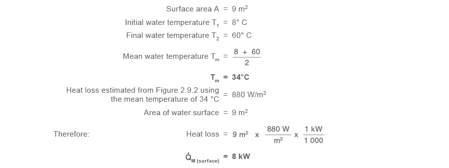
Part 1.4 Heat losses from liquid surface Q̇M (surface)
Part 1.5 Total mean heat transfer requirement Q̇M (start-up)

Part 2 - Determine the running load, that is the maximum heat transfer rate required during operation Q̇(operation)
In operating conditions, the liquid and tank (A1 and A2, page 2.9.6) are already up to operating temperature, so the heating components = 0.
In operating conditions, the heat losses from the liquid and tank (A3 and A4) will be greater. This is because of the greater difference between the liquid and tank temperatures and the surroundings.
Immersing the article in the liquid is clearly the objective of the process, so this heat load must be calculated and added to the running load heat losses.
Part 2.1 Heat losses from tank sides
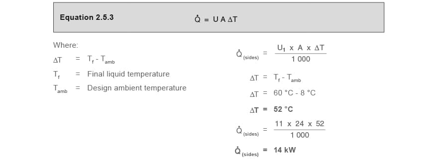
Part 2.2 Heat losses from liquid surface Q̇(surface)

Part 2.3 Heating the steel articles immersed in the tank Q̇(article)

Part 2.4 Total mean heat transfer requirements Q̇(operation) (The running load)

Note that the operational energy requirement (59 kW) is significantly less than the start-up energy requirement (367 kW). This is typical, and, where possible, the start-up period may be extended.
This will have the effect of reducing the maximum energy flowrate and has the benefits of levelling demand on the boiler, and making less demand on the temperature control system.
For tanks that are to operate continuously, it is often only necessary to calculate the operating requirements i.e. the Part 2 calculations.