Steam Engineering Principles and Heat Transfer

Contents
Methods of Estimating Steam Consumption
How to calculate steam requirements for flow and non-flow applications. Including warm-up, heat losses and running loads.
The optimum design for a steam system will largely depend on whether the steam consumption rate has been accurately established. This will enable pipe sizes to be calculated, while ancillaries such as control valves and steam traps can be sized to give the best possible results. The steam demand of the plant can be determined using a number of different methods:
Calculation
By analysing the heat output on an item of plant using heat transfer equations, it may be possible to obtain an estimate for the steam consumption. Although heat transfer is not an exact science and there may be many unknown variables, it is possible to utilise previous experimental data from similar applications. The results acquired using this method are usually accurate enough for most purposes.
Measurement
Steam consumption may be determined by direct measurement, using flowmetering equipment. This will provide relatively accurate data on the steam consumption for an existing plant. However, for a plant which is still at the design stage, or is not up and running, this method is of little use.
Thermal rating
The thermal rating (or design rating) is often displayed on the name-plate of an individual item of plant, as provided by the manufacturers. These ratings usually express the anticipated heat output in kW, but the steam consumption required in kg/h will depend on the recommended steam pressure.
A change in any parameter which may alter the anticipated heat output, means that the thermal (design) rating and the connected load (actual steam consumption) will not be the same. The manufacturer’s rating is an indication of the ideal capacity of an item and does not necessarily equate to the connected load.
Calculation
In most cases, the heat in steam is required to do two things:
1) To produce a change in temperature in the product, that is providing a ‘heating up’ component
2) To maintain the product temperature as heat is lost by natural causes or by design, that is providing a ‘heat loss’ component.
In any heating process, the ‘heating up’ component will decrease as the product temperature rises, and the differential temperature between the heating coil and the product reduces. However, the heat loss component will increase as the product temperature rises and more heat is lost to the environment from the vessel or pipework.
The total heat demand at any time is the sum of these two components.
The equation used to establish the amount of heat required to raise the temperature of a substance (Equation 2.1.4, from module 2), can be developed to apply to a range of heat transfer processes.
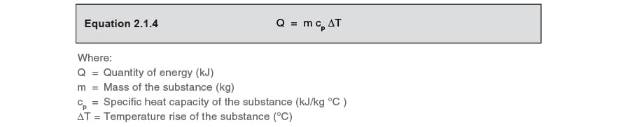
In its original form this equation can be used to determine a total amount of heat energy over the whole process. However, in its current form, it does not take into account the rate of heat transfer. To establish the rates of heat transfer, the various types of heat exchange application can be divided into two broad categories:
Non-flow type applications
where the product being heated is a fixed mass and a single batch within the confines of a vessel.
Flow type applications
where a heated fluid constantly flows over the heat transfer surface.
Non-flow type applications
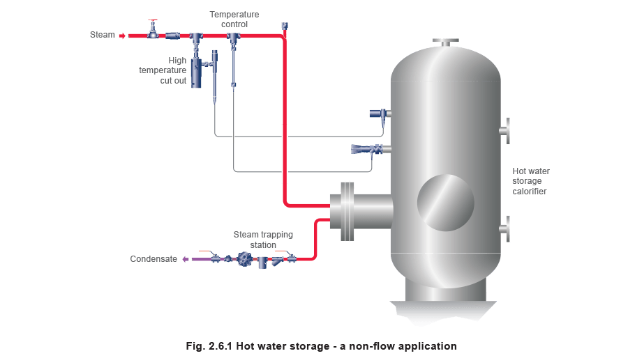
In non-flow type applications the process fluid is held as a single batch within the confines of a vessel. A steam coil situated in the vessel, or a steam jacket around the vessel, may constitute the heating surface. Typical examples include hot water storage calorifiers as shown in Figure 2.6.1 and oil storage tanks where a large circular steel tank is filled with a viscous oil requiring heat before it can be pumped. Some processes are concerned with heating solids; typical examples are tyre presses, laundry ironers, vulcanisers and autoclaves.
In some non-flow type applications, the process heat up time is unimportant and ignored. However, in others, like tanks and vulcanisers, it may not only be important but crucial to the overall process.
Consider two non-flow heating processes requiring the same amount of heat energy but different lengths of time to heat up. The heat transfer rates would differ while the amounts of total heat transferred would be the same.
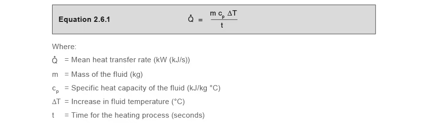
The mean rate of heat transfer for such applications can be obtained by modifying Equation 2.1.4 to Equation 2.6.1:
Example 2.6.1
Calculating the mean heat transfer rate in a non-flow application.
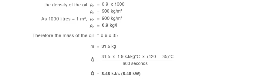
A quantity of oil is heated from a temperature of 35 °C to 120 °C over a period of 10 minutes (600 seconds). The volume of the oil is 35 litres, its specific gravity is 0.9 and its specific heat capacity is 1.9 kJ/kg °C over that temperature range.
Determine the rate of heat transfer required:
As the density of water at Standard Temperature and Pressure (STP) is 1 000 kg/m³
Equation 2.6.1 can be applied whether the substance being heated is a solid, a liquid or a gas.
However, it does not take into account the transfer of heat involved when there is a change of phase.
The quantity of heat provided by the condensing of steam can be determined by Equation 2.6.2:

It therefore follows that the steam consumption can be determined from the heat transfer rate and vice-versa, from Equation 2.6.3.

If it is assumed at this stage that the heat transfer is 100% efficient, then the heat provided by the steam must be equal to the heat requirement of the fluid to be heated. This can then be used to construct a heat balance, in which the heat energy supplied and required are equated:

Example 2.6.2
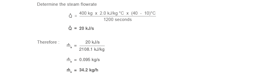
A A tank containing 400 kg of kerosene is to be heated from 10 °C to 40 °C in 20 minutes (1 200 seconds), using 4 bar g steam. The kerosene has a specific heat capacity of 2.0 kJ/kg °C over that temperature range. hfg at 4.0 bar g is 2 108.1 kJ/kg. The tank is well insulated and heat losses are negligible.
In some non-flow type applications, the length of time of the batch process may not be critical, and a longer heat up time may be acceptable. This will reduce the instantaneous steam consumption and the size of the required plant equipment.
Flow type applications
Typical examples include shell and tube heat exchangers, see Figure 2.6.2 (also referred to as non-storage calorifiers) and plate heat exchangers, providing hot water to heating systems or industrial processes. Another example would be an air heater battery where steam gives up its heat to the air that is constantly passing through.

Figure 2.6.3 provides a typical temperature profile in a heat exchanger with a constant secondary fluid flowrate. The condensing temperature (TS) remains constant throughout the heat exchanger.
The fluid is heated from T1 at the inlet valve to TS at the outlet of the heat exchanger.

For a fixed secondary flowrate, the required heat load (Q̇) is proportional to the product temperature rise (ΔT). Using Equation 2.6.1:

Mean steam consumption
The mean steam consumption of a flow type application like a process heat exchanger or heating calorifier can be determined from Equation 2.6.6, as shown in Equation 2.6.7.
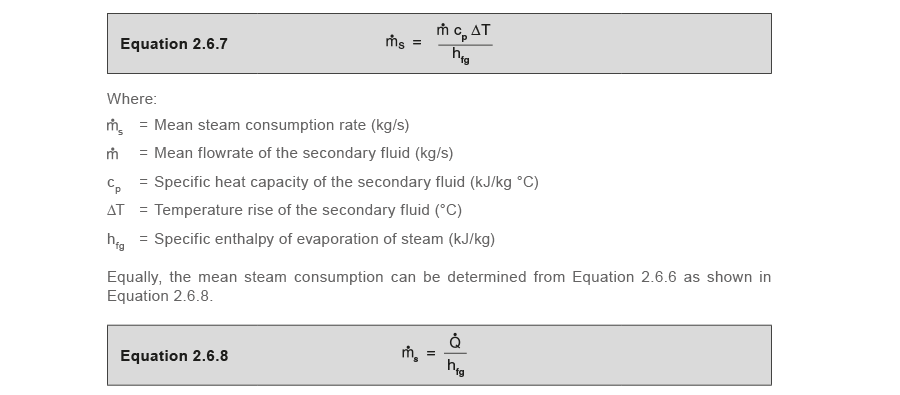
But as the mean heat transfer is, itself, calculated from the mass flow, the specific heat, and the temperature rise, it is easier to use Equation 2.6.7.
Example 2.6.3
Dry saturated steam at 3 bar g is used to heat water flowing at a constant rate of 1.5 l/s from 10°C to 60°C.
hfg at 3 bar g is 2 133.4 kJ/kg, and the specific heat of water is 4.19 kJ/kg °C
Determine the steam flowrate from Equation 2.6.7:
As 1 litre of water has a mass of 1 kg, the mass flowrate = 1.5 kg/s

At start-up, the inlet temperature, T1 may be lower than the inlet temperature expected at the full running load, causing a higher heat demand. If the warm-up time is important to the process, the heat exchanger needs to be sized to provide this increased heat demand. However, warm-up loads are usually ignored in flow type design calculations, as start-ups are usually infrequent, and the time it takes to reach design conditions is not too important. The heat exchanger heating surface is therefore usually sized on the running load conditions.
In flow type applications, heat losses from the system tend to be considerably less than the heating requirement, and are usually ignored. However, if heat losses are large, the mean heat loss (mainly from distribution pipework) should be included when calculating the heating surface area.
Warm-up and heat loss components
In any heating process, the warm-up component will decrease as the product temperature rises, and the differential temperature across the heating coil reduces. However, the heat loss component will increase as the product and vessel temperatures rise, and more heat is lost to the environment from the vessel or pipework. The total heat demand at any time is the sum of these two components.
If the heating surface is sized only with consideration of the warm-up component, it is possible that not enough heat will be available for the process to reach its expected temperature. The heating element, when sized on the sum of the mean values of both these components, should normally be able to satisfy the overall heat demand of the application.
Sometimes, with very large bulk oil storage tanks for example, it can make sense to maintain the holding temperature lower than the required pumping temperature, as this will reduce the heat losses from the tank surface area. Another method of heating can be employed, such as an outflow heater, as shown in Figure 2.6.4.

Heating elements are encased in a metal shroud protruding into the tank and designed such that only the oil in the immediate vicinity is drawn in and heated to the pumping temperature. Heat is therefore only demanded when oil is drawn off, and since the tank temperature is lowered, lagging can often be dispensed with. The size of outflow heater will depend on the temperature of the bulk oil, the pumping temperature and the pumping rate.
Adding materials to open topped process tanks can also be regarded as a heat loss component which will increase thermal demand. These materials will act as a heat sink when immersed, and they need to be considered when sizing the heating surface area.
Whatever the application, when the heat transfer surface needs calculating, it is first necessary to evaluate the total mean heat transfer rate. From this, the heat demand and steam load may be determined for full load and start-up. This will allow the size of the control valve to be based on either of these two conditions, subject to choice.