Steam Engineering Principles and Heat Transfer

Contents
Steam Consumption of Pipes and Air Heaters
Steam will condense and give up its enthalpy of evaporation on the walls of any pipe or tube at a lower temperature. It is not usually possible or necessary to calculate steam consumption exactly. This tutorial allows satisfactory estimates to be made for most practical purposes.
Steam will condense and give up its enthalpy of evaporation on the walls of any pipe or tube exposed to ambient air. In some cases, such as steam mains, heat transfer is minimised by the lagging of the pipes. In other cases such as air heater batteries, heat transfer may be promoted by the use of fins on the outside of the pipes.
It is not usually possible or necessary to calculate steam consumption exactly. The examples in this Module allow sufficient estimates to be made for most practical purposes.
Steam mains
In any steam system, the condensation of steam caused by the pipe itself must be taken into account. The rate of condensation will be at its highest during the warming up period, and it is this that should govern the size of steam traps used for mains drainage. With the steam main in use, there will also be a smaller (but continual) heat loss from the pipe. Both of these components can be calculated as the ‘warming up load’ and the ‘running load’.
Warm-up load
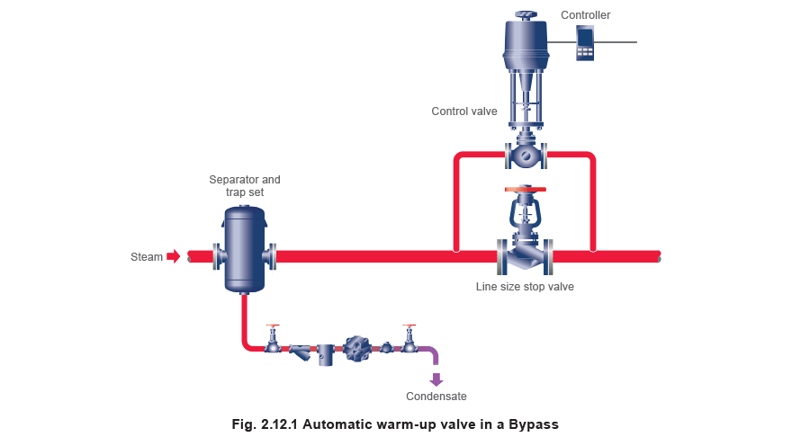
Heat will initially be required to bring the cold pipe up to working temperature. It is good practice to do this slowly for safety reasons, the pipes also benefit from reduced thermal and mechanical stress. This will result in fewer leaks, lower maintenance costs, and a longer life for the pipe. Slow warm-up can be achieved by fitting a small valve in parallel with the main isolating valve, (Figure 2.12.1). The valve can be sized depending on the warm-up time required. Automating the warm-up valve to open slowly on large pipes can improve safety.
A single main isolating valve can be used successfully, but, as it will be sized to pass the pipeline design flow requirements, it will be oversized during the warm-up period and will consequently operate very close to its seat at this time. A separator placed before the valve will ensure the steam passing through is dry, protecting the trim from premature wear.
The time taken to warm up any steam main should be as long as possible within acceptable limits to minimise mechanical pipework stress, optimise safety and reduce start-up loads.
If 10 minutes can be taken instead of 5 minutes, the initial steam flowrate will be reduced by half. A warm-up time of 20 minutes will reduce the warm-up load even further.
The steam flowrate required to bring a pipework system up to operating temperature is a function of the mass and specific heat of the material, the temperature increase, the enthalpy of evaporation of the steam used, and the allowable time.
This may be expressed by Equation 2.12.1:

Example 2.12.1 Heat losses from a steam pipeline
A system consists of 100 m of 100 mm carbon steel main, which includes 9 pairs of PN40 flanged joints, and one isolating valve.
cp for steel = 0.49 kJ/kg °C
The ambient/starting temperature is 20°C and the steam pressure is 14.0 bar g, 198°C from steam tables (see Table 2.12.2).
Table 2.12.2 Extract from steam tables
| Pressure bar g |
Saturation temperature °C |
Enthalpy (energy) in kJ/kg | Specific volume of dry saturated steam m3/kg |
||
| Water hf |
Evaporation hfg |
Steam hg |
|||
| 14 | 198 | 845 | 1 947 | 2 792 | 0.132 |
Determine:
Part 1. The warm-up condensing rate for a warm-up time of 30 minutes.
Part 2. The running load if the insulation thickness is 75 mm.
Part 1 Calculate the warm-up load
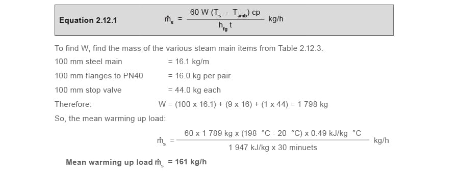
Note: This condensing rate will be used to select an appropriate warm-up control valve.
When selecting steam traps, this condensing rate should be multiplied by a factor of two to allow for the lower steam pressure that will occur until warm-up is completed, then divided by the number of traps fitted to give the required capacity of each trap.
Table 2.12.3 Typical weight of steel pipe, flanges and bolts, and isolating valves in kg
| Pipe size (mm) | Sch. 40 pipe kg/m | Flange weight per pair | Isolating valve flanged PN40 | ||
| PN40 | ASME (ANSI) 150 |
ASME (ANSI) 300 |
|||
| 15 | 1.3 | 1.7 | 1.8 | 2 | 4 |
| 20 | 1.7 | 2.3 | 2.2 | 3 | 5 |
| 25 | 2.5 | 2.6 | 2.4 | 4 | 6 |
| 32 | 3.4 | 4 | 3 | 6 | 8 |
| 40 | 4.1 | 5 | 4 | 8 | 11 |
| 50 | 5.4 | 6 | 6 | 9 | 14 |
| 65 | 8.6 | 9 | 8 | 12 | 19 |
| 80 | 11.3 | 11 | 11 | 15 | 26 |
| 100 | 16.1 | 16 | 16 | 23 | 44 |
| 150 | 28.2 | 28 | 26 | 32 | 88 |
Part 2 Running load
Steam will condense as heat is lost from the pipe to the environment: The rate of condensation depends on the following factors:
- The steam temperature.
- The ambient temperature.
- The efficiency of the lagging.
Table 2.12.4 gives typical heat emission rates expected from unlagged steel pipes in still air at 20°C.
Table 2.12.4 Heat emission from unlagged steel pipes freely exposed in air at 20 °C (W/m)
| Temperature differential steam to air °C | Pipe size (mm) | |||||||||
| 15 | 20 | 25 | 32 | 40 | 50 | 65 | 80 | 100 | 150 | |
| 50 | 56 | 68 | 82 | 100 | 113 | 136 | 168 | 191 | 241 | 332 |
| 60 | 69 | 85 | 102 | 125 | 140 | 170 | 208 | 238 | 298 | 412 |
| 70 | 84 | 102 | 124 | 152 | 170 | 206 | 252 | 289 | 360 | 500 |
| 80 | 100 | 122 | 148 | 180 | 202 | 245 | 299 | 343 | 428 | 594 |
| 100 | 135 | 164 | 199 | 243 | 272 | 330 | 403 | 464 | 577 | 804 |
| 120 | 173 | 210 | 256 | 313 | 351 | 426 | 522 | 600 | 746 | 1 042 |
| 140 | 216 | 262 | 319 | 391 | 439 | 533 | 653 | 751 | 936 | 1 308 |
| 160 | 263 | 319 | 389 | 476 | 535 | 651 | 799 | 918 | 1 145 | 1 603 |
| 180 | 313 | 381 | 464 | 569 | 640 | 780 | 958 | 1 100 | 1 374 | 1 925 |
| 200 | 368 | 448 | 546 | 670 | 754 | 919 | 1 131 | 1 297 | 1 623 | 2 276 |
| 220 | 427 | 520 | 634 | 778 | 877 | 1 069 | 1 318 | 1 510 | 1 892 | 2 655 |
Distribution mains will normally be lagged however, and is obviously an advantage if flanges and other items of pipeline equipment are lagged too. If the main is flanged, each pair of flanges will have approximately the same surface area as 300 mm of pipe of the same size.
The rate of heat transfer increases when a heat transfer surface is subjected to air movement. In these cases, the multiplication factors, as shown in Table 2.12.5, should be considered.
If finned or corrugated tubing is fitted, then the maker’s figures for heat emission should always be used.
In everyday terms, air velocities up to 4 or 5 m/s (approximately 10 mph) represent a gentle breeze, between 5 and 10 m/s (approximately 10 - 20 mph) a strong breeze. Typical air duct velocities are around 3 m/s, in comparison.
Table 2.12.5 Approximate increase in emission due to air movement over pipes with a high emissivity
| Air velocity (m/s) |
Emission factor |
| 0 | 1 |
| 0.5 | 1 |
| 1 | 1.3 |
| 1.5 | 1.5 |
| 2 | 1.7 |
| 2.5 | 1.8 |
| 3 | 2 |
| 4 | 2.3 |
| 6 | 2.9 |
| 8 | 3.5 |
| 10 | 4 |
Note: Exact figures are difficult to determine, as many factors are involved. The factors in Table 2.12.5 are derived and give a rough indication of how much the figures in Table 2.12.4 should be multiplied. Pipes subjected to air movement up to around 1 m/s can be thought of as being in still air, and heat losses are fairly constant up to this point. As a guide, painted pipes will have a high emissivity, oxidised steel a medium emissivity, and polished stainless steel a
low emissivity.
The reduction in heat losses will depend on the type and thickness of the lagging material used, and on its general condition. For most practical purposes, the lagging of steam lines will reduce the heat emissions in Table 2.12.4 by the insulation factors (f) shown in Table 2.12.6.
Note that these factors are nominal values only. For specific calculations, consult the insulation manufacturer.
Table 2.12.6 Insulation factors ‘f’
| Pipe size NB (mm) | Steam pressure | |||
| 1 bar g | 5 bar g | 15 bar g | 20 bar g | |
| 50 mm insulation | ||||
| 15 | 0.16 | 0.14 | 0.13 | 0.12 |
| 20 | 0.15 | 0.13 | 0.12 | 0.11 |
| 25 | 0.14 | 0.12 | 0.11 | 0.1 |
| 32 | 0.13 | 0.11 | 0.1 | 0.1 |
| 40 | 0.12 | 0.11 | 0.1 | 0.09 |
| 50 | 0.12 | 0.1 | 0.09 | 0.08 |
| 65 | 0.11 | 0.1 | 0.09 | 0.08 |
| 80 | 0.1 | 0.1 | 0.08 | 0.07 |
| 100 | 0.1 | 0.09 | 0.08 | 0.07 |
| 150 | 0.1 | 0.09 | 0.07 | 0.07 |
| 75 mm insulation | ||||
| 15 | 0.14 | 0.13 | 0.12 | 0.11 |
| 20 | 0.13 | 0.11 | 0.11 | 0.1 |
| 25 | 0.13 | 0.11 | 0.1 | 0.09 |
| 32 | 0.11 | 0.1 | 0.09 | 0.08 |
| 40 | 0.1 | 0.09 | 0.09 | 0.08 |
| 50 | 0.1 | 0.09 | 0.08 | 0.07 |
| 65 | 0.1 | 0.08 | 0.08 | 0.07 |
| 80 | 0.09 | 0.08 | 0.07 | 0.07 |
| 100 | 0.08 | 0.08 | 0.07 | 0.06 |
| 150 | 0.08 | 0.07 | 0.07 | 0.06 |
| 100 mm insulation | ||||
| 15 | 0.12 | 0.11 | 0.1 | 0.08 |
| 20 | 0.11 | 0.1 | 0.09 | 0.07 |
| 25 | 0.1 | 0.09 | 0.08 | 0.07 |
| 32 | 0.1 | 0.08 | 0.08 | 0.06 |
| 40 | 0.09 | 0.08 | 0.08 | 0.06 |
| 50 | 0.08 | 0.08 | 0.07 | 0.06 |
| 65 | 0.08 | 0.07 | 0.06 | 0.05 |
| 80 | 0.07 | 0.07 | 0.06 | 0.05 |
| 100 | 0.07 | 0.07 | 0.06 | 0.05 |
| 150 | 0.07 | 0.06 | 0.05 | 0.04 |
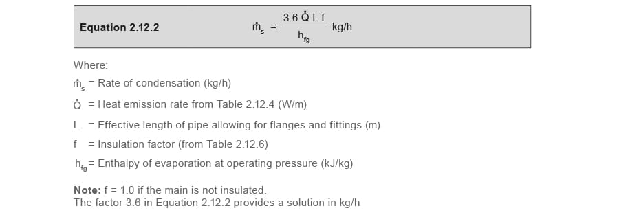
The heat loss from insulated mains can be expressed as follows in Equation 2.12.2:
Determine the length, L:
Assuming an allowance equivalent to 0.3 m for each pair of flanges, and 1.2 m for each stop valve, the total effective length (L) of the steam main in this example is:

Determine the heat emission rate, Q̇:
The temperature of the steam at 14.0 bar gauge is 198 °C and, with the ambient temperature 20 °C, the temperature difference is 178 °C.
From Table 2.12.4: Heat loss for a 100 mm pipe ≈ 1 374 W / m
Determine the insulation factor, f:
The insulation factor for 75 mm insulation on 100 mm pipe at 14 bar g (from Table 2.12.6) is approximately 0.07.

As can be seen from this example, the warm-up load of 161 kg/h (see Example 2.12.1, Part 1) is substantially greater than the running load of 18.3 kg/h, and, in general, steam traps sized on the warm-up duty will automatically cater for the running load.
If the steam line above was unlagged or the lagging was damaged, the running load would have been approximately fourteen times greater.
With an uninsulated pipe, or a poorly insulated pipe, always compare the running and warm-up loads. The higher load should be used to size the steam traps, as described above. Ideally, the quality of insulation should be improved.
Note: When calculating warming up losses, it is sensible to consider the correct pipe specification, as pipe weights can vary between different pipe standards.
Air heating
The density and specific heat of air changes slightly with temperature. For most practical purposes, when heating air for HVAC and process applications with the approach mentioned below, a nominal figure of 1.3 kJ/m³ °C can be used for specific heat and 1.3 kg/m3 for density.
Air heating pipes
Heated air is required for many applications including:
- Space heating.
- Ventilation.
- Process applications.

The equipment required often consists of a matrix of tubes filled with steam, installed across an air stream. As the air passes over the tubes, heat is transferred from the steam to the air. Often, in order to minimise the size and mass of the equipment, and allow it to be installed in confined spaces with reduced support works, and to limit the cost, the rate of heat transfer from the tubes to the air is increased by the addition of fins to the outer wall of the tube.
This has the effect of increasing the heat transfer area available, and thus reducing the amount of piping required. Figure 2.12.2 shows an example of a finned tube.
Broadly, air heaters may be divided into two categories:
- Unit heaters.
- Air heater batteries.
Unit heaters
These consist of a heater battery and fan in one compact casing (Figure 2.12.3). The primary medium (steam) condenses in the heater battery, and air is warmed as it blows across the coils and is discharged into the space.
Unit heaters can be arranged to have fresh air inlet ducting, but more often operate with recirculated air.

The warm air can be discharged vertically downwards or horizontally. Steam pressure, mounting heights, the type of discharge and leaving temperatures are all inter-related and the manufacturer’s data should be consulted before selecting the unit heater. Most units are available with low, medium or high speed fans which affect the rated output, and again the manufacturer’s data should be consulted, as the noise levels on high speed may be unacceptable.
Air heater batteries
These are really larger and more sophisticated versions of unit heaters, see Figure 2.12.4. They are available in many configurations including roof mounted, or horizontal types, and a fan and filter may also be incorporated. They are usually integrated into a ducted air system.
- Adjustable louvres may be provided to adjust the ratio of fresh to recirculated air.
- A number of heater banks may be incorporated to provide frost protection.

Manufacturers of unit heaters and air heater batteries usually give the output of their heaters in kW at a working pressure. From this, the condensing rate can be calculated by dividing the heat output by the enthalpy of evaporation of steam at this pressure. The solution will be in kg/s; multiplying by 3 600 (seconds in an hour) will give the solution in kg/h.
Thus a 44 kW unit heater working at 3.5 bar g (hfg = 2 120 kJ/kg from steam tables) will condense:

Note: The constant 3 600 is included in the formula to give flowrate in kg/h rather than kg/s. If the manufacturer’s figures are not available but the following are known:
- The volumetric flowrate of air being heated.
- The temperature rise of the air being heated.
- The steam pressure in the heater.
Then the approximate rate of condensation can be calculated using Equation 2.12.3:
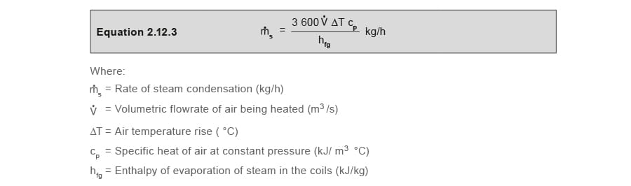
Note: The constant 3 600 gives the solution in kg/h rather than kg/s.
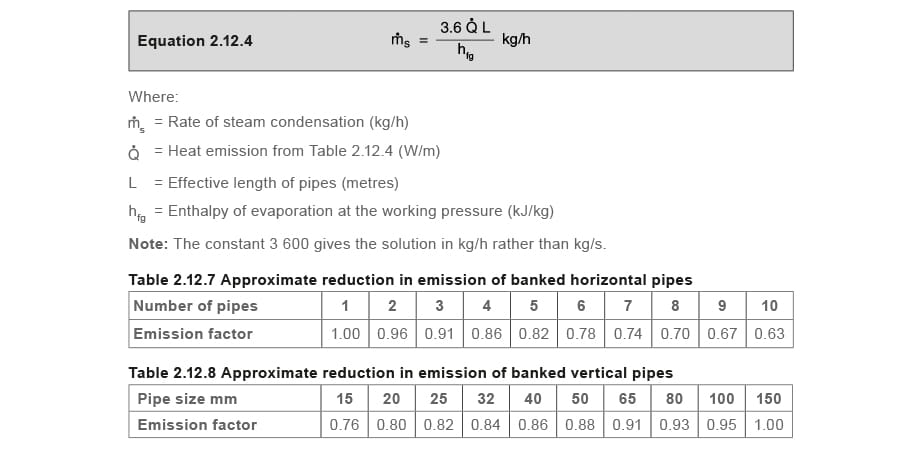
Horizontal pipes assembled into coils with several rows of pipes one above the other, and relying upon natural convection, become less effective as the number of pipes is increased. When calculating the rate of condensation for such coils, the figures given in Table 2.12.5 should be multiplied by the emission factors in Table 2.12.7.
Vertically installed heating pipes are also less effective than horizontal pipes. The condensation rate of such pipes can be determined by multiplying the figures in Table 2.12.4 by the factors in Table 2.12.6.
Table 2.12.7 can also be used to find the rate of condensation in horizontal pipes used for heating still air. In this instance use the Equation 2.12.4:
Effects of air flowrate
When a fan is used to increase the flow of air over pipe coils, the rate of condensation will increase. The figures for heat emission from bare steel pipes (Table 2.12.4), can be used when multiplied in accordance with the factors in Tables 2.12.5, 2.12.7 and 2.12.8 where appropriate.
If finned tubing is being considered, then the maker’s figures for heat emission should be used in all cases.
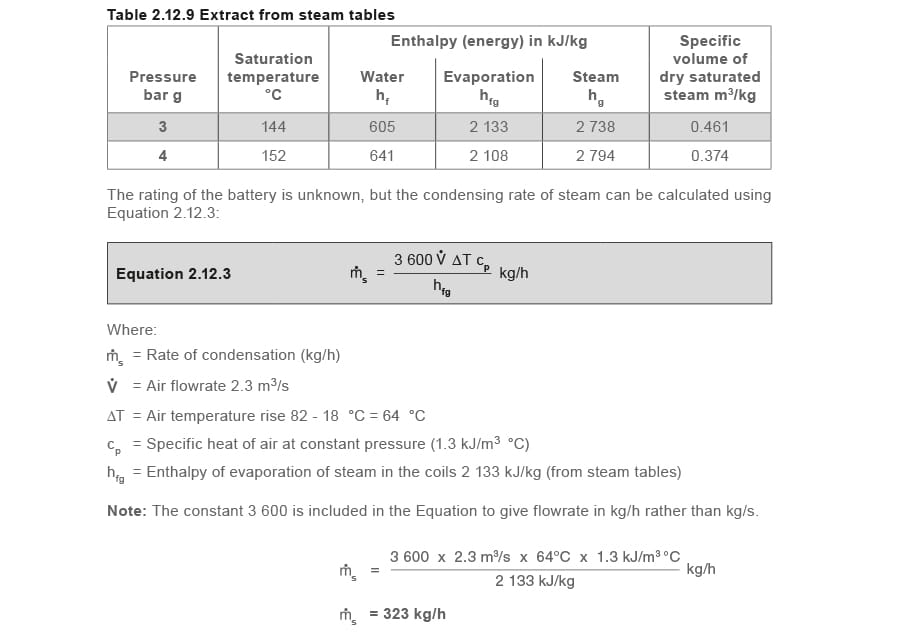
Example 2.12.2 Calculate the steam load on an air heater battery
An air heater battery raises the temperature of air flowing at 2.3 m³/s from 18 °C to 82 °C (ΔT = 64 °C) with steam at 3.0 bar g in the coils.