Steam Traps and Steam Trapping

Contents
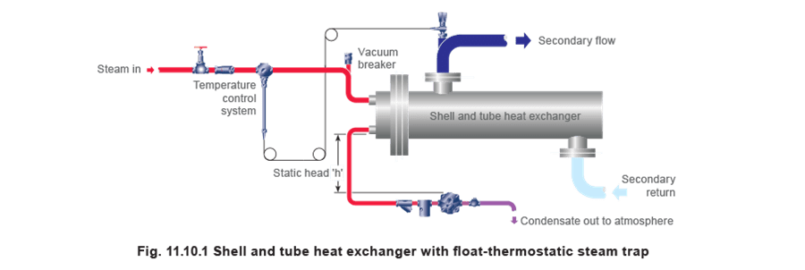
Selecting Steam Traps - Space Heating Equipment
A - Best choice, B - Acceptable alternative, 1 (parallel air vent), 4 (a pump/trap may be required).
Heat exchangers draining to atmospheric pressure
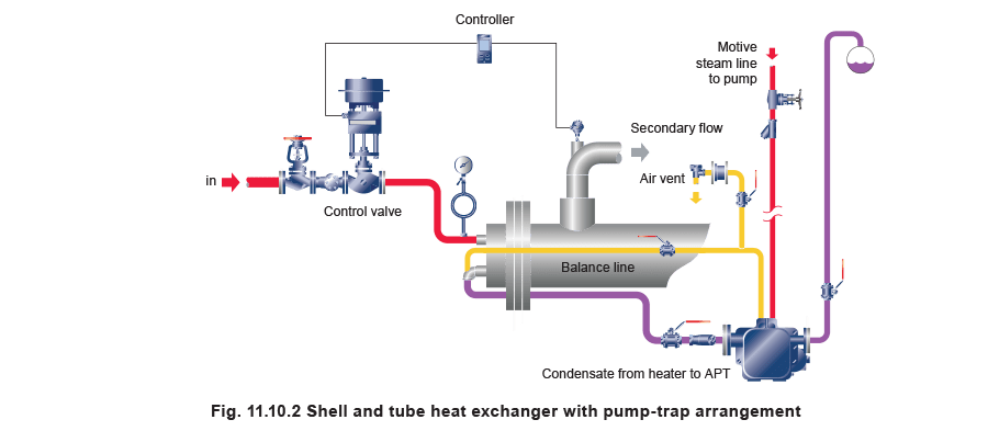
The trap for this application must be able to handle a very heavy or very light load equally well, and be able to purge air quickly. The float-thermostatic trap is ideal and should always be installed below the outlet of the heat exchanger. Figure 11.10.1 shows a float-thermostatic trap with no backpressure imposed by the condensate system, such as would be found if condensate were draining to a receiver vented to atmosphere, or to a lower, non-flooded condensate return line.
Whenever the output of the heater is controlled, the effect is to reduce the pressure in the steam space, which may then become insufficient to push the condensate through the trap, and the system is said to have ‘stalled’. The pressure will reduce to below atmospheric pressure (i.e. vacuum) if the secondary water temperature is controlled to below 100°C. Vacuum retains the condensate which waterlogs the heater tubes. This can cause waterhammer, poor temperature control and, in most cases, eventual corrosion of the heater elements.
On smaller heat exchangers which drain to atmosphere, a simple remedy is to install a vacuum breaker on the steam inlet to the heat exchanger (see Figure 11.10.1). When vacuum occurs in the steam space, the vacuum breaker opens to allow the condensate to drain down to the steam trap.
The trap itself must be placed below the exchanger outlet, and must be sized to pass the condensate stall load on the static head ‘h’ (created by the height of the outlet above the trap inlet). The condensate pipe from the trap should slope downwards so that no further backpressure is exerted on the trap.
Heat exchangers draining to a positive pressure
Often, and especially on larger plant, it is usually preferable not to introduce air into the steam space, and the use of a vacuum breaker may not be tolerated. Also, if the condensate lifts after the steam trap up to a higher level, a vacuum breaker cannot assist drainage. In these situations, a pump-trap or pump/trap combination should be used.
If stall is inevitable and a vacuum breaker cannot be used, an active method of condensate removal must be used to give good system performance. A pump-trap (as shown in Figure 11.10.2), will perform as a steam trap if there is sufficient steam pressure in the steam space to overcome the backpressure. If there is not, it will act as a pump. The device is fully self-contained and automatic in its operation.
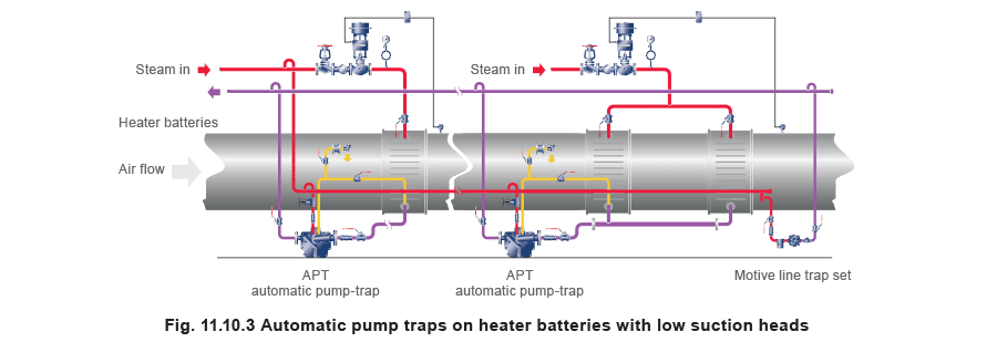
The pump-trap is also extremely useful where restricted space exists below the heater, for example on air handling units which are often positioned close to the plant room floor. Figure 11.10.3 shows an example draining single and multi-heater batteries to avoid both freezing and corrosion of the coils.
When a pump-trap arrangement is used, condensate will always be removed from the heater under all pressure conditions, ensuring maximum system efficiency at all times, with no escape of flash steam in the plant room.
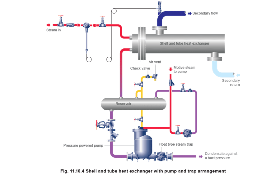
Where plant capacity is too large for the pump-trap, it can be replaced by a separate pump and steam trap in combination, such as that shown in Figure 11.10.4. A pressure powered pump is dedicated to a single heater, connected so that the pump chamber, piping, and the steam side of the heater tubes form a common steam space. When the steam pressure is sufficiently high, condensate flows from the steam space and through the pump body and steam trap into the condensate system. When the pressure is lowered as the control valve throttles, condensate fills the pump chamber till full. When the pump chamber is full, a mechanism triggers allowing 'motive' steam to enter the chamber. This pushes condensate out of the chamber and away through the trap.
The pump exhaust line is connected to a reservoir and acts as a balance pipe when the pump is filling. The small amount of exhaust steam is then contained within the system, and pumping occurs with no waste of steam to atmosphere. The system will be energy efficient, and the plant room will be free from flash steam.
If it can be guaranteed that the condensate pressure will always be higher than the steam pressure in the steam space, a trap does not need to be installed with the pump.
Further details on the subject of condensate drainage from temperature controlled heat exchangers can be found in Block 13, 'Condensate Removal'.
Radiant panels and strips
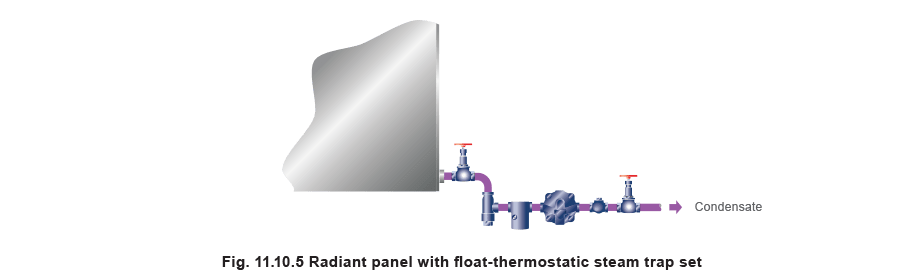
Heat output depends on high surface temperature, consequently prompt condensate removal is vital. Best results are achieved by trapping each panel individually with a float trap which handles air and condensate quickly (Figure 11.10.5). Grouping two similar panels to one trap is often satisfactory. Thermodynamic or inverted bucket traps can also be used, but supplementary air vents may be necessary.
Steam radiators
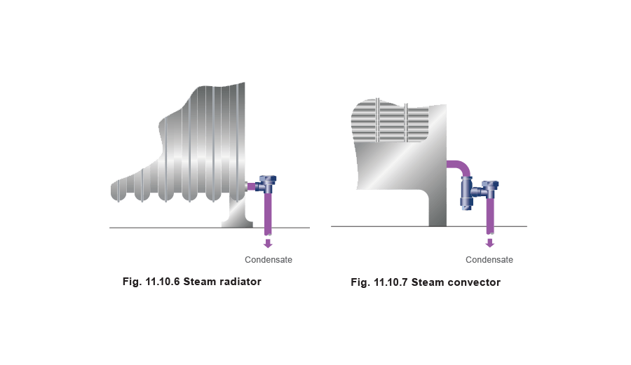
For the standard type of steam radiator which normally operates at pressures below 2 bar g, a balanced pressure thermostatic steam trap, with union inlet may be used, as shown in Figure 11.10.6. A strainer may not be needed as the radiator collects dirt and can be blown through once a year after temporarily removing the trap capsule. When replacing the capsule, it is useful to ensure the valve and seat faces are clean.
If, however, it is preferred to incorporate a strainer, a balanced pressure trap with strainer is a useful alternative (Figure 11.10.7). In some installations, this type of heater is used in conjunction with a vacuum return system, in which case a special sub-cooled capsule is available.
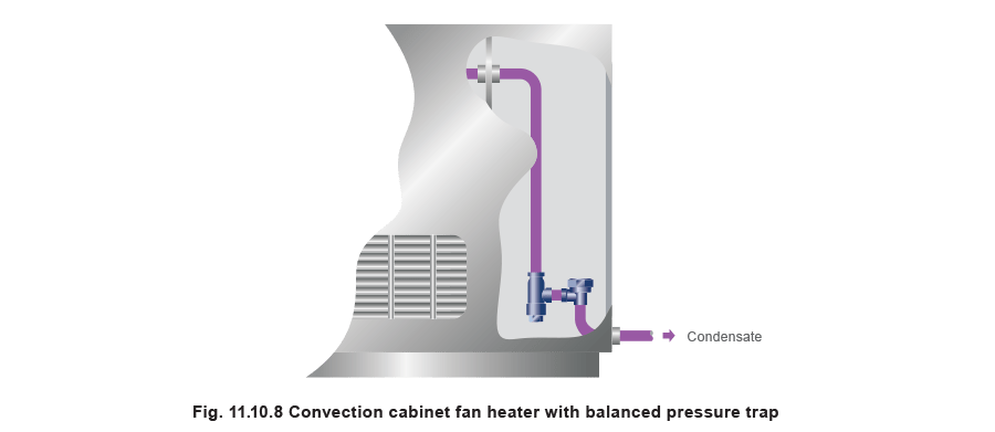
Convection cabinet fan heaters
Although these heaters have a small steam space and condensate must not be allowed to build up, design factors call for a neat layout. A balanced pressure trap can provide this, as shown in Figure 11.10.8. If, however, the cabinet is of the forced draught design (with inbuilt fan), the higher duty requires that the steam space should be kept clear of condensate and air. A float trap is ideal but fitting it neatly inside the cabinet may present a problem. A satisfactory alternative is a balanced pressure trap, as Figure 11.10.8 illustrates, to allow a maximum length of cooling leg.
Unit heaters and air heater batteries
Unit heaters and air heater batteries produce a lot of condensate from a small steam space. Any accumulation of condensate or air produces uneven temperatures or cold air and may eventually damage the heater battery. Use a small float-thermostatic trap close to the inlet (Figure 11.10.9).

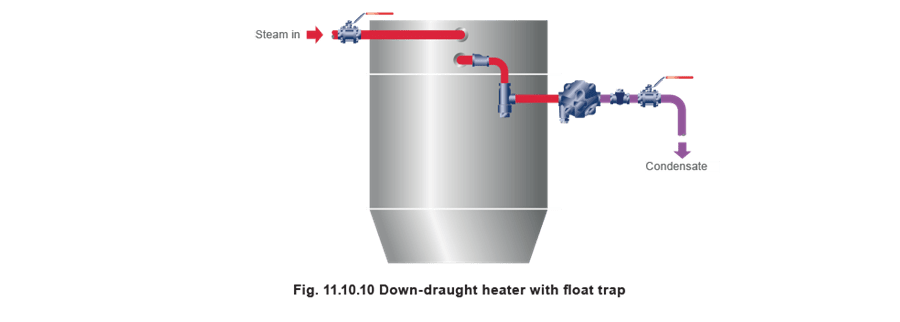
With horizontal batteries such as those used in down-draught heaters, any reduction in the condensate outlet pipe must be made using an eccentric reducer. This will stop condensate backing up in the coils. The trap should be fitted below the outlet as in Figure 11.10.10. Condensate clearance can be improved by fitting the heater battery with a slight fall towards the outlet end.
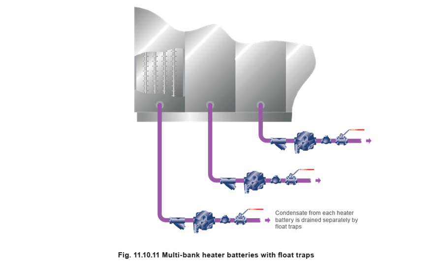
Where a number of vertical heater batteries are installed in series with the air flow, successive sections do progressively less work and produce progressively less condensate. Each section should be drained separately with a float trap (Figure 11.10.11). If a float trap is not used, the inverted bucket trap is a possible alternative, but with an air vent fitted in parallel.
When higher pressure steam is used in a multi-heater bank system, savings can be achieved by collecting the condensate, separating the flash steam and using it to heat the first heater section in the bank. When the heater batteries are temperature controlled, stall conditions can occur in the steam spaces preventing efficient condensate removal. A Spirax Sarco vacuum breaker should be fitted to the pipework between the control valve and the heater battery inlet, and the condensate pipework must be allowed to fall to a collecting point i.e. a receiver vented to atmosphere. The float trap must be sized on the stall load. The subject of stall is considered in detail in Block 12.
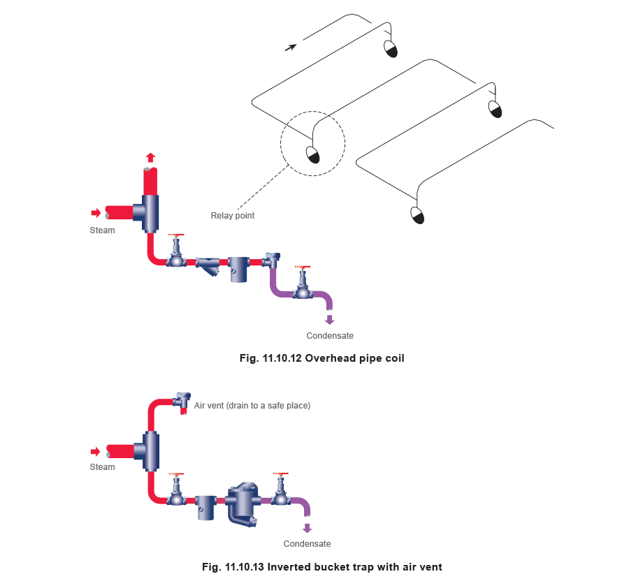
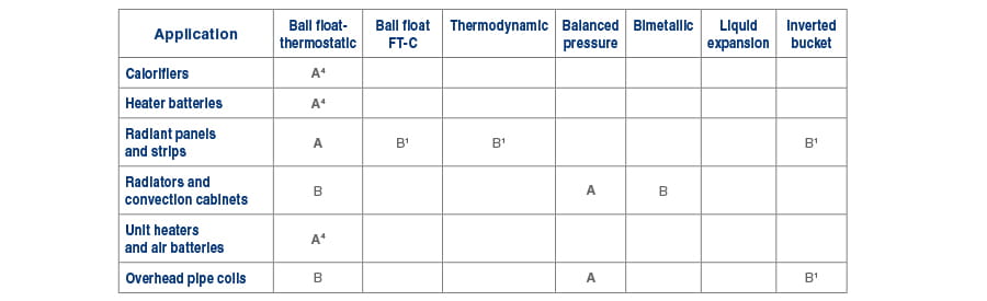
Overhead pipe coils
Long overhead heating pipes, like industrial drying coils, will produce waterhammer if insufficient attention is given to installation. Heat will circulate slowly and temperature control will be difficult. Relaying the pipework as in Figure 11.10.12, using balanced pressure traps with stainless steel capsules, or with float or inverted bucket traps will eliminate these problems. With inverted bucket traps, warm-up speed can be greatly improved by fitting separate air vents, especially on the end of the coil (Figure 11.10.13).