The Boiler House

Contents
Heat Recovery from Boiler Blowdown (TDS control only)
Boiler water is blown down to control the amount of total dissolved solids (TDS) in the boiler. This water is pressurised, hot and dirty, creating large volumes of flash steam and possible disposal problems. A heat recovery system can reclaim large amounts of energy during this essential process.
Heat Recovery from Boiler Blowdown (TDS control only)
The previous module discussed the water to be blown down from a boiler in order to maintain an acceptable TDS level. This water has a number of characteristics:
- It is dirty - This means that:
-The water is generally unsuitable for other applications.
-The dirty water may present a disposal problem.
- It is hot - This means that:
-A proportion of the water will flash to steam at atmospheric pressure.
-The hot water may present a disposal problem. For example, there may be a substantial quantity to dispose of.
A heat recovery system can solve many of these problems.
Energy flowrate in blowdown
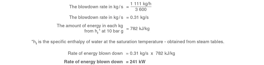
Using the data from the blowdown calculation, Example 3.12.5, the amount of energy sent to blowdown can be calculated using the steam tables.
Note: 1 kJ/s = 1 kW
Example 3.13.1

To obtain the energy flow in kW:
To put the energy flowrate into context, in North West Europe the average domestic central heating system is rated at approximately 13 kW, so the energy flowrate blown down in Example 3.13.1 is sufficient to heat 19 houses.
For clarity the above calculation utilises steam tables where water at 0°C is the datum.
In reality, make-up water to replace the blowdown will be supplied at a temperature greater than this, so the energy blow down will be slightly less. For example, if the make-up water were at 10°C the energy blown down would be 228 kW.
Flash steam
The blowdown water released from the boiler is water at the saturation temperature appropriate to the boiler pressure. In the case of the boiler in Example 3.13.1 - 10 bar g, this temperature is 184°C. Clearly, water cannot exist at 184°C under atmospheric conditions, because there is an excess of enthalpy or energy in the blowdown water.
Assuming the blowdown water is released to a flash steam system operating at 0.5 bar g, steam tables may be used to quantify this energy excess:

This excess energy evaporates a proportion of the water to steam, and the steam is referred to as flash steam.
The quantity of flash steam is readily determined by calculation or can be read from tables or charts.
Example 3.13.2
The specific enthalpy of evaporation at 0.5 bar g (hfg) from steam tables is 2 226 kJ/kg.

Therefore 14.1% of the water blown down from the boiler will change to steam as its pressure drops from 10 to 0.5 bar g across the blowdown valve.
There are two options:
- Vent this flash steam to atmosphere via the blowdown vessel with the associated waste of energy and potentially good quality water from the condensed steam.
- Utilise the energy in the flash steam, and recover water by condensing the flash steam. It is useful to quantify the energy flowrate in the flash steam. This can be done using steam tables.
Example 3.13.3
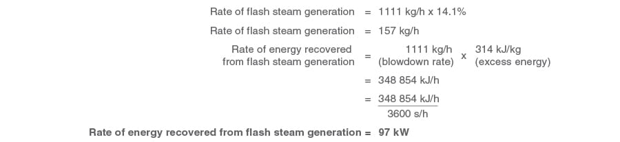
Compare this to the 241 kW rate of energy blown down from the boiler.
It may be possible to use this flash steam: in this example it represents approximately 49% of the energy flowrate in the blowdown, and 14.1% of the water blown down.
Using values from steam tables for the above calculations assumes that feedwater will be supplied at a temperature of 0°C. For greater accuracy, the actual change in feedwater temperature should be used.
Recovering and using flash steam
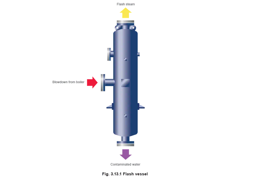
The flash steam becomes available for recovery at the flash vessel. In essence, a flash vessel provides a space where the velocity is low enough to allow the hot water and flash steam to separate, and from there to be piped to different parts of the plant.
The design of the flash vessel is important not only from a steam/water separation point of view, but structurally it should be designed and built to a recognised pressure vessel standard, such as PD 5500.
This is not only good engineering practice, the boiler inspector will also insist upon this if the plant is to be insured.
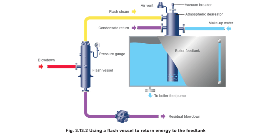
The most obvious place for the flash steam to be used is in the boiler feedtank, which is usually nearby.
The water temperature in the feedtank is important. If it is too low, chemicals will be required to de-oxygenate the water; if it is too high the feedpump may cavitate. Clearly, if heat recovery is likely to result in an excessive high feedtank temperature, it is not practical to discharge flash steam into the tank. Other solutions are possible, such as feedwater heating on the pressure side of the feedpump, or heating the combustion air.
Figure 3.13.2 shows a simple installation, which makes recovery of the 97 kW of energy flow, and 157 kg/h of boiler quality water, extremely cost effective.
Equipment required
- Flash vessel - Manufacturers will have sizing charts for vessels. Note: the steam velocity in the top section of the vessel should not exceed 3 m/s.
- Steam trap to drain the vessel - A float trap is ideal for this application as it releases the residual blowdown water as soon as it reaches the trap.
The flash vessel is working at low pressure so there is virtually no energy to lift the residual blowdown after the steam trap, so this must drain by gravity through the trap and discharge pipework.
Note: because of the low pressure, the trap will be fairly large. This has the additional advantage that it is unlikely to be blocked by the solids in the residual blowdown water.
Sometimes strainers are preferred before the steam trap; for this application the strainer cap should be fitted with a blowdown valve to simplify maintenance, and the strainer screen should not be too fine.
- Vacuum breaker - There will be occasions when the boiler does not need to blow down. At these times any steam in the flash vessel and associated pipework will condense and a vacuum will be formed. If this vacuum is not released then water will be drawn up from the boiler feedtank into the pipework. When the boiler blows down again this water will be forced along the pipe at high velocity and waterhammer will occur.
A vacuum breaker fitted to the deareator head will protect against this eventuality.
- Steam distribution equipment - Proper distribution of the flash steam in the feedwater tank is clearly important in order to ensure condensation and recovery of the heat and water. The equipment required to do this include, in order of effectiveness:
1. Atmospheric deaerator.
2. team distributor.
3. Sparge pipe.
Heat recovery using heat exchangers
Heat recovery from residual blowdown
About 40% of the energy in boiler blowdown can be recovered through the use of a flash vessel and associated equipment; however, there is scope for further heat recovery from the residual blowdown itself.
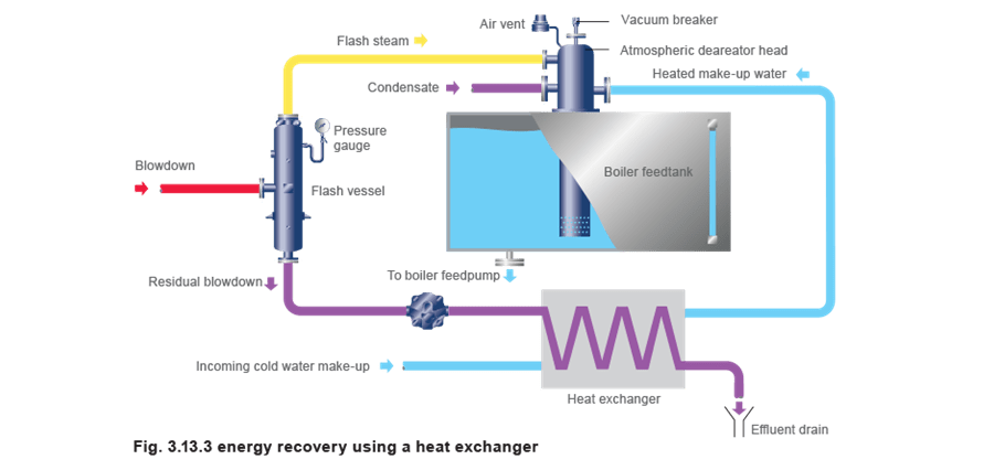
Continuing on from Example 3.13.3, if the flash vessel operates at a pressure of 0.5 bar g, this means that the residual blowdown passes through the flash vessel float trap at about 105°C. Further useful energy can be recovered from the residual blowdown before passing it to drain. The accepted method is to pass it through a heat exchanger, heating make-up water en route to the feedtank. This approach typically cools the residual blowdown to about 20°C. This system not only recovers the energy in the blowdown effluent, it also cools the water before discharging into the drainage system. (The temperature at which effluent may be discharged is limited to 42°C in the UK; other countries having similar limitations).
Example 3.13.4
(continuing from Example 3.13.3)

A typical arrangement for recovering this energy is shown in Figure 3.13.3.
Design consideration
A problem with the arrangement shown in Figure 3.13.3 is that the simultaneous flow of incoming cold make-up water and residual blowdown from the flash vessel may not be guaranteed.
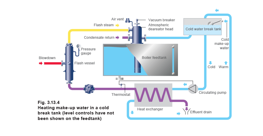
One preferred arrangement is shown in Figure 3.13.4, where a cold water break tank is used as a heat sink. A thermostat is used to control a small circulating pump so that when the residual blowdown is at a high enough temperature, water is pumped through the heat exchanger, raising the average tank temperature and saving energy.
If the temperature of the blowdown effluent exiting the heat exchanger can be above 43°C, then it should be directed to the blowdown vessel rather than straight to the effluent drain (See Module 3.14).
Preferred type of heat exchanger
Plate heat exchangers are preferred for this application, as they are very compact and easily maintained.
Experience shows that the higher velocities and turbulence in plate heat exchangers help to keep them clean, and hence dismantling is rarely required. However, should cleaning be required, it is relatively straightforward to open the heat exchanger and clean the plates.
The cleaning of a shell and tube heat exchanger is more complex, and will involve a complete strip down and often the tubes themselves cannot be removed for cleaning.

When energy is recovered from the flash steam and the condensate, 82% of the total energy contained in the original blowdown has been recovered.
In addition, 14% (by mass) of the water has been recovered, making a further contribution to savings.