Condensate Removal

Contents
Practical Methods of Preventing Stall
This tutorial considers methods of overcoming condensate drainage problems, such as ensuring gravity drainage, installing an automatic pump trap device, or controlling the pressure in the steam space.
Practical Methods of Preventing Stall
If stall conditions are inevitable, potential problems can be overcome by designing the installation around one of three basic solutions:
- Ensure the steam pressure in the steam space can never drop below atmospheric pressure, and that the condensate can drain by gravity to and from a ball float steam trap.
- Accept that the pressure in the steam space may be less than the backpressure, and provide an alternative means of removing condensate, by installing a pump-trap.
- Ensure the pressure in the steam space is stable and higher than the backpressure. This will entail having the temperature control system on the secondary side of the system
Taking these three options in turn:
- Installations that ensure the conditions in the steam space can never drop below atmospheric pressure, and that the condensate can drain by gravity to and from a steam trap:
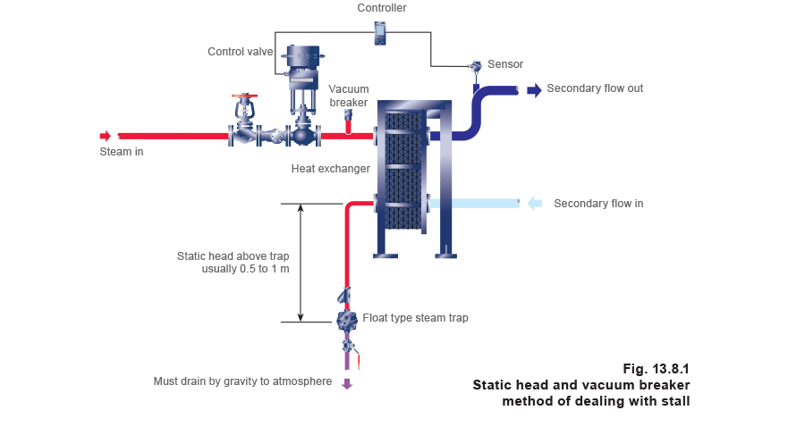
1a) Condensate removal by vacuum breaker method (see Figure 13.8.1)
The steam trap cannot be subject to any backpressure higher than atmospheric, and must drain condensate either to an open end (which may be wasteful), or to a nearby vented receiver and pump, enabling the energy contained in the condensate to be reclaimed.
There are two criteria that must be satisfied:
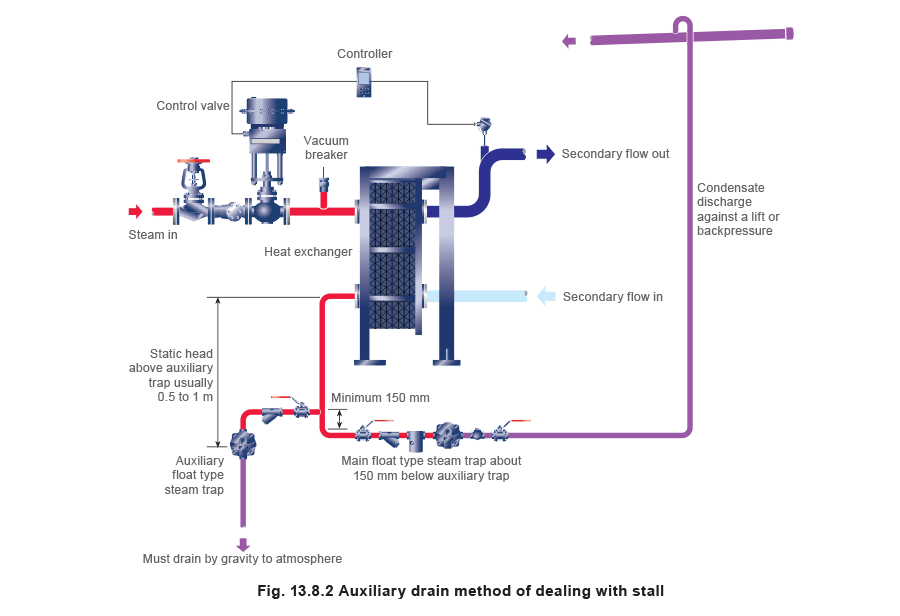
1b) Auxiliary drain trap method (see Figure 13.8.2)
A standard float trap set is installed with condensate returning to a condensate system, which is either pressurised and/or elevated above the trap. An auxiliary float trap may be fitted, discharging condensate via an open end to drain.
When there is sufficient steam pressure to overcome the backpressure, the main float trap will function, but when stall occurs, condensate will back-up and drain through the auxiliary float trap thus preventing condensate flooding back into the heat exchanger.
As this condensate will drain to waste, this method should only be used if stall occurs infrequently. The auxiliary trap should be sized on static head to pass the stall load as in method 1a, and the ‘main’ trap should be the same size, but fitted at least 150 mm below the auxiliary take-off tee-piece.
Apart from the obvious disadvantage of energy loss, this method also requires available head between the trap inlets and the heat exchanger outlet.
2. Installations which allow the steam pressure in the steam space to drop below the backpressure, but where the condensate can drain by gravity to a pump-trap arrangement:
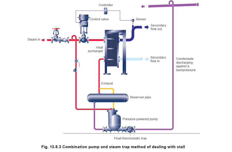
2a) A pump and float trap installed in combination (see Figure 13.8.3)
This method uses a pump and float trap installed in combination. It is better suited to heat exchangers with nominal heating capacities in excess of 1.5 MW (nominally 2 500 kg/h of steam).
The steam pressure changes relative to changes in heat load. At high loads the steam pressure will be higher than the backpressure, but at low loads it will be lower.
The pump is a mechanical pressure-powered type, in which an auxiliary steam supply automatically takes over to provide the motive power to discharge the condensate when stall occurs. If the steam space pressure is higher than the backpressure, condensate passes through the pump body to the float trap, which allows the condensate to discharge.
This method is more practical and economical on larger installations; for example, those using condensate drain lines of 40 mm or more.
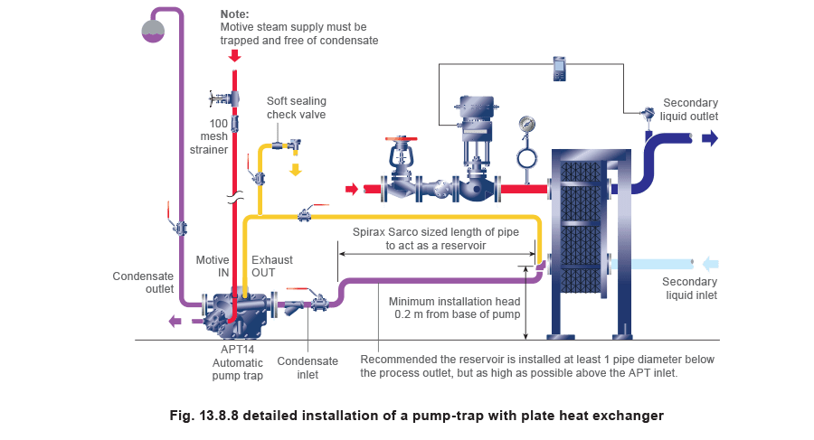
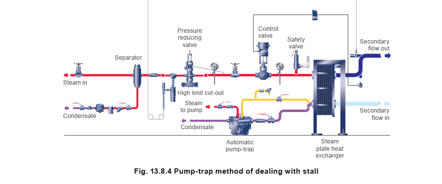
2b) A pump-trap with constant flow heat exchanger (see Figure 13.8.4)
The secondary flowrate does not change as it passes through the heat exchanger, consequently the steam pressure changes relative to changes in the secondary inlet temperature. At high loads the steam pressure will be higher than the backpressure, but at low loads it will be lower.
This method uses a pump-trap device, which offers the functions of a pump, steam trap and check valves in one body.
The Spirax Sarco APT14 automatic pump-trap is designed to occupy a minimum amount of space, and can be fitted to heat exchangers with nominal heating capacity of up to 1.5 MW.
It is most suited to installations with condensate drain lines up to 25 mm, but can be used on drain lines up to 40 mm in some circumstances.
A typical installation is shown on Figure 13.8.4.
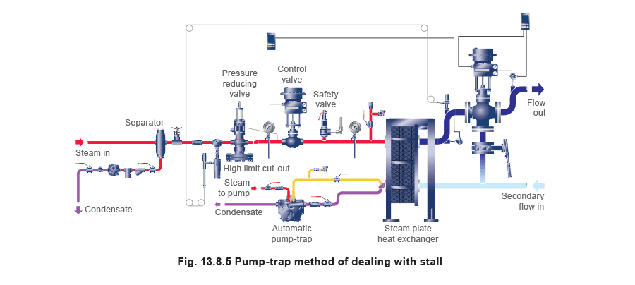
2c) A pump-trap device with varying flow heat exchanger (see Figure 13.8.5)
This method is similar to 2b), but the secondary flow through the heat exchanger varies with the heat load, due to the action of the secondary mixing valve.
The heat exchanger delivers a constant temperature water flow which is blended by the secondary mixing valve according to load. As the secondary flow varies, the steam pressure changes to maintain a constant outlet temperature, such that, at high loads, it is above the backpressure, and at low loads it is below.
3. Installations which ensure the steam pressure is kept constant and can never drop below the backpressure, and that the condensate can drain to and from a steam trap:
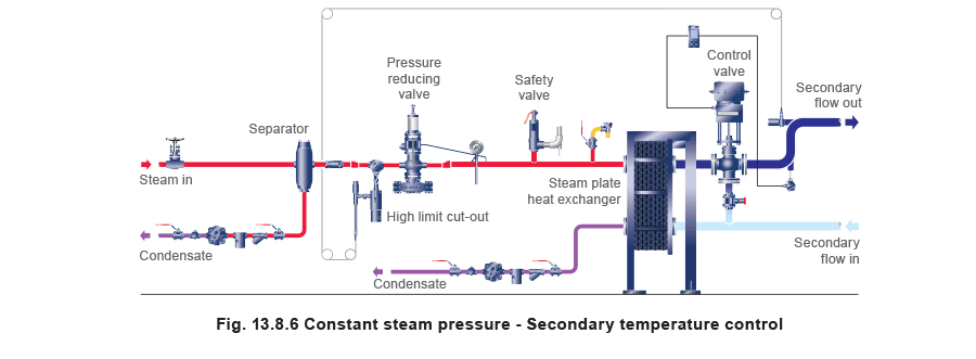
3a) Steam trap with temperature control valve in secondary circuit (see Figure 13.8.6)
This method requires temperature control to be carried out with a 3-port mixing or diverting valve in the secondary circuit. The steam supply to the heat exchanger is held at a constant pressure (usually less than 1 bar g) with a pressure control valve, and as such, condensate can always be cleared from the heat exchanger against a lower backpressure.
This method is not always practical or possible. It is unsuitable on steam/air heater batteries or liquid systems where the secondary system is at such a low pressure that it is unable to prevent the liquid from boiling.
Like all methods, it has both advantages and disadvantages, which must be assessed before an option can be chosen.
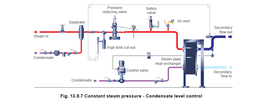
3b) Steam trap and modulating valve in condensate drain line (see Figure 13.8.7)
Condensate drainage is achieved with a modulating valve in the condensate drain line. This method also maintains the desired steam pressure in the steam space regardless of load conditions.
However, it encourages (instead of eliminates) waterlogging in the heat exchanger, as control is achieved by deliberately flooding the steam space with condensate as the load reduces. Usually this method is only considered if:
On/off control should not be used with heat exchangers
An on/off temperature control valve does not modulate depending on heat load, but is either fully open or fully closed. An example would be a solenoid valve. When open, full steam pressure will be maintained in the heat exchanger to clear the condensate against the backpressure. At first glance, this method of control would seem to overcome any backpressure problems, but is not recommended on processes such as heat exchangers, where the secondary fluid has to be heated to its required temperature as it passes through. There are three main reasons for this:
- An ‘on/off’ control system is activated by a thermostat which relies upon a product overtemperature to achieve control. As steam has high heat content, a significant amount of heat can be held in the steam space after the solenoid valve has shut. The overall effect is a higher product temperature than required. Should the thermostat setting be lowered to counteract this effect, the ‘on’ temperature may be lower than the system parameters may require. It can result in poor control of the system temperature and the potential for product spoilage.
- The continual and rapid changes in pressure and temperature will impose thermal and mechanical stresses upon the heat exchanger which will probably reduce its service life.
- It is never a good idea to subject steam systems to an instantaneous increase in pressure. Any condensate present in the steam space and condensate pipe is instantly pushed, by the sudden inrush of steam, through the system towards the steam trap. This can cause waterhammer, and damage the heat exchanger and steam trap.
On/off control is normally only suitable for ‘non-flow’ or ‘batch’ type heat exchange processes, notably tanks with robust heating coils, or jacketed pans, where the desired steam pressure is applied over a long heating up period (usually over many minutes or even hours). The rise in product temperature is much slower than that experienced with flow-type systems that are expected to heat the product in the short time it takes to pass through a heat exchanger.
Conclusion
The most suitable type of steam trap for heat exchange equipment in general, and especially if stall is likely, is a ball float steam trap with integral balanced pressure air vent.
If there is any likelihood of stall, a pump-trap is generally the most effective way of dealing with it, as it benefits from being:
- Simple.
- Cost effective.
- Compact.
Please note: The diagrams in this Module are schematic only, and for simplicity do not contain all the ancillary equipment that would be necessary or advisable for a specific installation. The exception is Figure 13.8.8, which shows a detailed, actual, installation of an APT14 automatic pump-trap.