Control Applications

Contents
Level Control Applications
A range of level control systems and methods are used in industry. Systems may be based on the use of floats, probes or even more sophisticated technology. This tutorial studies the use of probes to provide adjustable & non-adjustable on/off control, and modulating control of liquids. Simple flow control applications are also considered.
The control of liquid levels, for example in a process tank, is an important function. An example would be a hot water tank where water is removed, perhaps for washing down, and the level needs to be restored ready for the next wash cycle.
Control of water level and alarms for steam boilers is specifically excluded from this Module, and the reader is referred to Block 3 (The Boiler House), which deals with the subject in depth.
Many different types of level control systems are used in industry, covering a wide range of processes. Some processes will be concerned with media other than liquids, such as dry powders and chemical feedstock. The range of media is so wide that no single instrument is suitable forall applications.
Many systems are available to serve this wide range of applications. The following list is not exhaustive but, in most cases, the final control signal will be used to operate pumps or valves appropriate to the application:
Float operated types – a float rises and falls according to the change in liquid level and operates switches at predetermined points in the range.
Solid probe types – these measure conductivity or capacitance and are discussed in more detail in the following pages.
Steel rope capacitance types – a flexible steel rope is suspended in the liquid, and the change in capacitance is measured relative to the change in water level.
Ultrasonic types – a high frequency acoustic pulse is directed down from a transducer to the surface of the medium being measured and, by knowing the temperature and speed of sound in air, the time it takes for the pulse to rebound to the sensor is used to determine the level.
Microwave radar types – similar in principle to the ultrasonic type but using high frequency electromagnetic energy instead of acoustic energy.
Hydrostatic types – a pressure transmitter is used to measure the pressure difference between the confined hydrostatic pressure of the liquid head above the sensor and the outside atmospheric pressure. Changes in pressure are converted into a 4-20 mA output signal relative to the head difference.
Differential pressure types – similar to hydrostatic but used where the application being measured is subjected to dynamic pressure in addition to static pressure. They are capable of measuring small changes in pressure in relation to the output signal range. Typical applications might be to measure the level of water in a boiler steam drum, or the level of condensate in a reboiler condensate pocket.
Magnetic types – a float or cone is able to rise and fall along a stainless steel probe held in the tank fluid being measured. The float can interact magnetically with switches on the outside of the tank which send back information to the controller.
Torsion types – a moving float spindle produces a change in torsion, measured by a torsion transducer.
It is important that the level control system is correct for the application, and that expert advice is sought from the manufacturer before selection.
It is not within the scope of this Module to discuss the pros and cons and potential applications of all the above control types, as the types of level control systems usually employed in the steam and condensate loop and its associated applications are float and solid probe types. The operation of float types is fairly self-explanatory, but conductivity and capacitance probes may require some explanation. Because of this, this section will mainly focus on conductivity and capacitance probetype level controls.
Methods of achieving level control
There are three main methods of achieving level control:
- Non-adjustable on/off level control.
- Adjustable on/off level control.
- Modulating level control.
Non-adjustable on/off level control (Figure 8.3.1)
The final control element may be a pump which is switched on/off or a valve which is opened/closed.
Two main types of on/off level control systems are usually encountered; float operated types and types using conductivity probes. Float type level controls either rely upon the direct movement of a control valve, or upon electrical switches being operated by a float moving on the surface of the liquid. Conductivity probes (see Figure 8.3.1) may have several probe tips; the control points being located where the separate tips have been cut to different lengths.

Adjustable on/off level control (Figure 8.3.2)
Again, the final control element may be a pump which is switched on/off or a valve which is opened/closed. One method used to adjust the control points is that of a capacitance probe (see Figure 8.3.2). The probe will monitor the level, with control points adjusted by the controller. Capacitance probes are not cut to length to achieve the required level and, of course, the whole probe length must be sufficient for the complete control range.
Modulating level control (Figure 8.3.2)
The final control element may be a valve that is adjusted to a point between fully open and fully closed, as a function of the level being monitored. Modulating level control cannot be achieved using a conductivity probe. Capacitance probes are ideal for this purpose (see Figure 8.3.2).
In systems of this type, the pump can run continuously, and the valve will permit appropriate quantities of liquid to pass. Alternatively, the final control element may be a variable speed drive on a pump. The speed of the drive may be adjusted over a selected range.
Alarms – are often required to warn of either:
- A high alarm where there is a danger of the tank overflowing and hot liquid being spilled, with the attendant danger to personnel.
- A low alarm where there is a danger of the tank water level becoming too low, with the potential to damage a pump drawing from the tank, or running out of liquid for the process.
Installation of floats and probes in turbulent conditions
In some tanks and vessels, turbulent conditions may exist, which can result in erratic and unrepresentative signals. If such conditions are likely to (or already) exist, it is recommended that floats or probes be installed within protection tubes. These have a dampening effect on the water level being sensed. The rest of this Module concerns itself with probes rather than floats for level control applications.
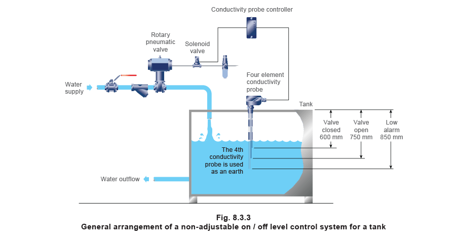
Non-adjustable on/off level control
Description
Non-adjustable on/off level control uses a conductivity probe connected to an electronic controller. The probe typically has three or four tips, each of which is cut to length during installation to achieve the required switching or alarm level (see Figure 8.3.3).
- When the tip of the probe is immersed in liquid it uses the relatively high conductivity of the water to complete an electrical circuit via the tank metalwork and the controller.
- When the water level drops below the tip, the circuit resistance increases considerably, indicating to the controller that the tip is not immersed in the liquid.
- In the case of a simple ‘pumping in’ system with on/off level control:
- The valve is opened when the tank water level falls below the end of a tip.
- The valve is closed when the water level rises to contact another tip.
- Other tips may be used to activate low or high alarms.
Advantage:
A simple but accurate and relatively inexpensive method of level control.
Applications:
The system can be used for liquids with conductivities of 1 μS/cm or more, and is suitable for condensate tanks, feedwater tanks and process vats or vessels. Where the conductivity falls below this level it is recommended that capacitance based level controls are used.
Point to note:
If the tank is constructed from a non-conductive material, the electrical circuit may be achieved via another probe tip.
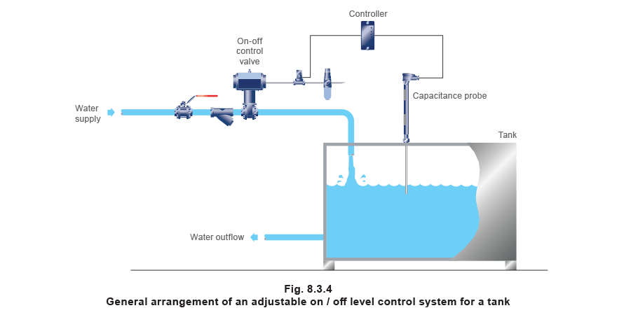
Adjustable on/off level control
Description
An adjustable on/off level control system consists of a controller and a capacitance probe (see Figure 8.3.4), and provides:
- Valve open/closed control plus one alarm point.
- Alternatively two alarms - high and low.
The levels at which the valve operates can be adjusted through the controller functions.
Advantage:
Adjustable on/off level control allows the level settings to be altered without shutting down the process.
Disadvantage:
More expensive than non-adjustable on/off control.
Applications:
Can be used for most liquids, including those with low conductivities.
Point to note:
Can be used in situations where the liquid surface is turbulent, and the in-built electronics can be adjusted to prevent rapid on/off cycling of the pump (or valve).
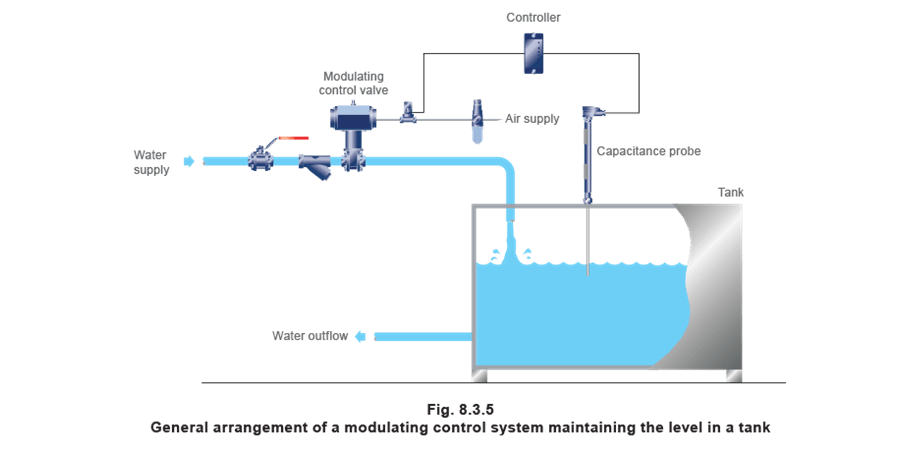
Modulating level control
Description
A modulating level control system consists of a capacitance probe and appropriate controller, which provides a modulating output signal, typically 4-20 mA. Refer to Figure 8.3.5. This output signal may be used to affect a variety of devices including:
- Modulating a control valve.
- Operating a variable speed pump drive.
Advantage:
- Because the probe and controller only provide a signal to which other devices respond, rather than providing the power to operate a device, there is no limit on the size of the application.
- Steady control of level within the tank.
Disadvantage:
- More expensive than a conductivity probe system.
- More complex than a conductivity probe system.
- Supply system must be permanently charged.
- Less suitable for ‘stand-by’ operation.
- Possibly greater electricity consumption.
Point to note:
To protect the supply pump from overheating when pumping against a closed modulating valve, a re-circulation or spill back line is provided to ensure a minimum flowrate through the pump (neither shown in Figure 8.3.5).
Steam flow control applications
The control of steam flow is less common than pressure and temperature control, but it is used in applications where the control of pressure or temperature is not possible or not appropriate to achieving the process objectives. The following sections give more information on measuring and controlling the flow of steam.
Flow control system
Typical applications:
- Feed-forward systems on boiler plant, where the rate of steam flow from the boiler will influence other control points, for example: feedwater make-up rate, and burner firing rate.
- Rehydration processes, where a measured quantity of steam (water) is injected into a product, which has been dried for transportation or storage. Examples of this can be found in the tobacco, coffee and animal feedstuff industries.
- Batch processes, where it is known from experience that a measured quantity of steam will produce the desired result on the product.
The selection and application of components used to control flowrate require careful thought.
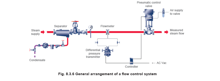
The flowmeter (pipeline transducer)
The flowmeter is a pipeline transducer, which converts flow into a measurable signal. The most commonly used pipeline transducer is likely to relate flow to differential pressure. This pressure signal is received by another transducer (typically a standard DP (differential pressure) transmitter) converting differential pressure into an electrical signal. Some pipeline transducers are capable of converting flowrate directly to an electrical signal without the need for a DP transmitter.
Figure 8.3.6 shows a variable area flowmeter and standard DP transmitter relating differential pressure measured across the flowmeter into a 4 - 20 mA electrical signal. The standard DP transmitter is calibrated to operate at a certain upstream pressure; if this pressure changes, the output signal will not represent the flow accurately. One way to overcome this problem is to provide a pressure (or temperature) signal if the medium is saturated steam, or a pressure and temperature signal if the fluid is superheated steam, as explained in the next Section. Another way is to use a mass flow DP transmitter, which automatically compensates for pressure changes.
The possible need for a computer
If steam is the fluid in the pipeline, then other temperature and/or pressure sensors may be necessary to provide signals to compensate for variations in the supply pressure, as shown in Figure 8.3.7.
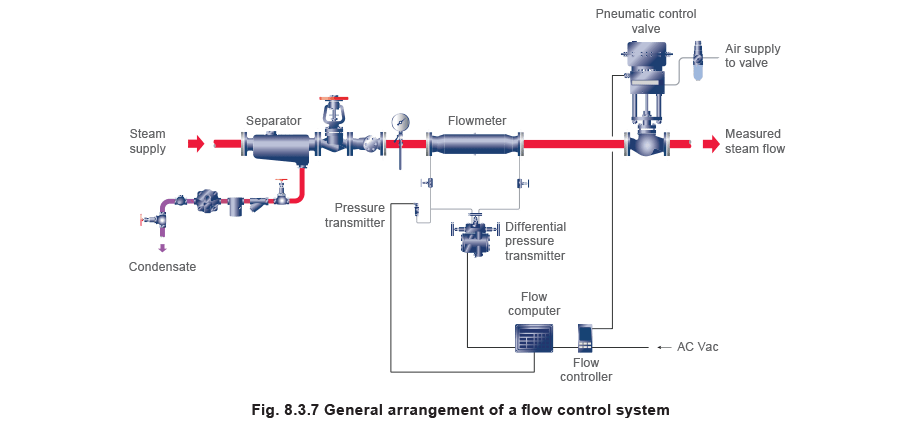
Multiple inputs will mean that an additional flow computer (or PLC) containing a set of electronic steam tables must process the signals from each of these flow, pressure and temperature sensors to allow accurate measurement of saturated or superheated steam.
If a flow computer is not readily available to compensate for changes in upstream pressure, it may be possible to provide a constant pressure; perhaps by using an upstream control valve, to give stable and accurate pressure control (not shown in Figure 8.3.7).
The purpose of this pressure control valve is to provide a stable (rather than reduced) pressure, but it will inherently introduce a pressure drop to the supply pipe.
A separator placed before any steam flowmetering station to protect the flowmeter from wet steam will also protect the pressure control valve from wiredrawing.
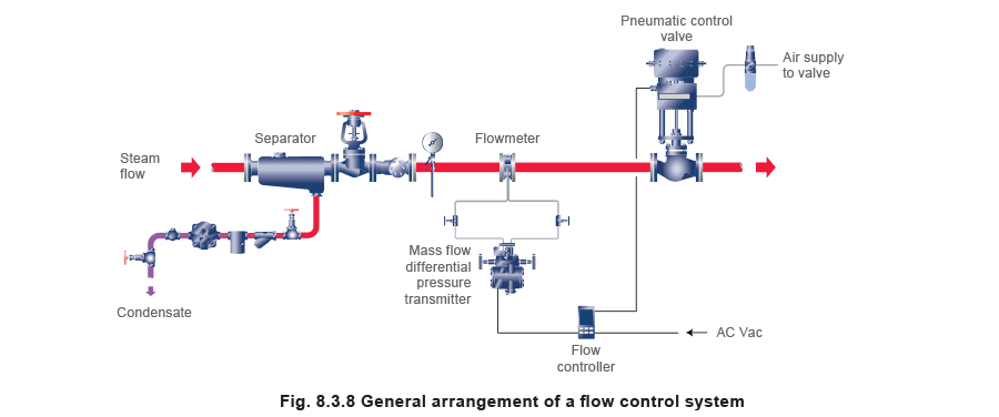
Using a mass flow DP transmitter
By using a mass flow DP transmitter instead of a standard DP transmitter, the need for a computer to provide accurate measurement is not required, as shown in Figure 8.3.8.
This is because the mass flow transmitter carries its own set of steam tables and can compensate for any changes in saturated steam supply pressure.
However, a computer can still be used, if other important flowmetering information is required, such as, the times of maximum or minimum load, or is there is a need to integrate flow over a certain time period.
A controller is still required if flowrate is to be controlled, whichever system is used.
The controller
Even if the output signal from the DP transmitter or computer is of a type that the control valve actuator can accept, a controller will still be required (as for any other type of control system) for the following reasons:
- The output signal from certain flowmeters/computers has a long time repeat interval (approximately 3 seconds), which will give enough information for a chart recorder to operate successfully, but may not offer enough response for a control valve. This means that if the controller or PLC to which the transmitter signal is being supplied operates at higher speeds, then the process can become unstable.
- PID functions are not available without a controller.
- Selecting a set point would not be possible without a controller.
- The signal needs calibrating to the valve travel - the effects of using either a greatly oversized or undersized valve without calibration, can easily cause problems.
Summary
It is usually better to install the flowmetering device upstream of the flow control valve. The higher pressure will minimise its size and allow it to be more cost effective. It is also likely that the flowmeter will be subjected to a more constant steam pressure (and density) and will be less affected by turbulence from the downstream flow control valve.
In some cases, the application may be required to control at a constant flowrate. This means that features, such as high turndown ratios, are not important, and orifice plate flowmeters are appropriate.
If the flowrate is to be varied by large amounts, however, then ‘turndown‘ becomes an issue that must be considered.
The subject of Flowmetering is discussed in greater depth in Block 4.