Control Hardware Electric-Pneumatic Actuation

Contents
Control Valve Sizing For Steam Systems
Sizing a control valve for a steam application can be a complex matter. This Module attempts to throw light on the subject by using first principles to explain the relationship between flow and pressure drop. It uses a simple nozzle to explain the phenomenon of critical pressure, and how this can be predicted for steam flow through a control valve. It continues by discussing other properties such as noise, erosion, and how steam is dried or superheated as it passes through a valve, and gives various examples of such calculations. It also briefly compares shell & tube and plate heat exchangers, and shows how to use simple Kv charts to size steam valves.
Before discussing the sizing of control valves for steam systems, it is useful to review the characteristics of steam in a heat transfer application.
- Steam is supplied at a specific pressure to the upstream side of the control valve through which it passes to a heat exchanger, also operating at a specific pressure.
- Steam passes through the control valve and into the steam space of the equipment where it comes into contact with the heat transfer surfaces.
- Steam condenses on the heat transfer surfaces, creating condensate.
- The volume of condensate is very much less than steam. This means that when steam condenses, the pressure in the steam space is reduced.
- The reduced pressure in the steam space means that a pressure difference exists across the control valve, and steam will flow from the high-pressure zone (upstream of the control valve) to the lower pressure zone (the steam space in the equipment) in some proportion to the pressure difference and, ideally, balancing the rate at which steam is condensing.
- The rate of steam flow into the equipment is governed by this pressure difference and the valve orifice size. Should, at any time, the flowrate of steam through the valve be less than the condensing rate (perhaps the valve is too small), the steam pressure and the heat transfer rate in the heat exchanger will fall below that which is required; the heat exchanger will not be able to satisfy the heat load.
- If a modulating control system is used, as the temperature of the process approaches the controller set point, the controller will close the valve by a related amount, thereby reducing the steam flowrate to maintain the lower pressure required to sustain a lower heat load. (The action of opening and closing the valve is often referred to as increasing or decreasing the ‘valve lift’; this is explained in more detail in Module 6.5, ‘Control Valve Characteristics’).
- Closing the valve reduces the mass flow. The steam pressure falls in the steam space and so too the steam temperature. This means that a smaller difference in temperature exists between the steam and the process, so the rate of heat transfer is reduced, in accordance with Equation 2.5.3.
The overall heat transfer coefficient (U) does not change very much during the process, and the area (A) is fixed, so if the mean temperature difference
ΔTm is reduced, then the heat transfer from the steam to the secondary fluid is also reduced.
Saturated steam flow through a control valve
A heat exchanger manufacturer will design equipment to give a certain heat output. To achieve this heat output, a certain saturated steam temperature will be required at the heat transfer surface (such as the inside of a heating coil in a shell and tube heat exchanger). With saturated steam, temperature and pressure are strictly related; therefore controlling the steam pressure easily regulates the temperature.
Consider an application where steam at 10 bar g is supplied to a control valve, and a given mass flow of steam passes through the valve to a heat exchanger. The valve is held fully open (see Figure 6.4.1).
- If a DN50 valve is fitted and the valve is fully open, the pressure drop is relatively small across the valve, and the steam supplied to the heat exchanger is at a fairly high pressure (and temperature). Because of this, the heating coil required to achieve the design load is relatively small.
- Consider now, a fully open DN40 valve in the steam supply line passing the same flowrate as the DN50 valve. As the valve orifice is smaller the pressure drop across the valve must be greater, leading to a lower pressure (and temperature) in the heat exchanger. Because of this, the heat transfer area required to achieve the same heat load must be increased. In other words, a larger heating coil or heat exchanger will be required.
- Further reduction of the valve size will require more pressure drop across the control valve for the same mass flow, and the need for an increased heat transfer surface area to maintain the same heat output.

Whatever the size of the control valve, if the process demand is reduced, the valve must modulate from the fully open position towards closed. However, the first part of the travel has only a small regulating effect, with any percentage change in valve lift producing a lesser percentage change in flowrate. Typically, a 10% change in lift might produce only a 5% change in flowrate. With further travel, as the valve plug approaches the seat, this effect reverses such that perhaps a 5% change in lift might produce a 10% change in flowrate, and better regulation is achieved.
The initial part of the control valve travel, during which this lowered control effect is seen, is greater with the selection of the larger control valves and the accompanying small pressure drop at full load. When the control valve chosen is small enough to require a ‘critical pressure drop’ at full load the effect disappears. Critical pressure is explained in the Section below.
Further, if a larger control valve is selected, the greater size of the valve orifice means that a given change in flowrate is achieved with a smaller percentage change in lift than is needed with a smaller control valve.
This can often make the control unstable, increasing the possibility of ‘hunting’, especially on reduced loads.
Critical pressure
The mass flow of steam passing through the valve will increase in line with differential pressure until a condition known as ‘critical pressure’ is reached. The principle can be explained by looking at how nozzles work and how they compare to control valves.
Consider an almost perfect orifice, such as a convergent-divergent nozzle shown in Figure 6.4.2. Its shape, if designed correctly to match the upstream and downstream pressure conditions and the condition of the supplied steam, will allow it to operate at high efficiency.
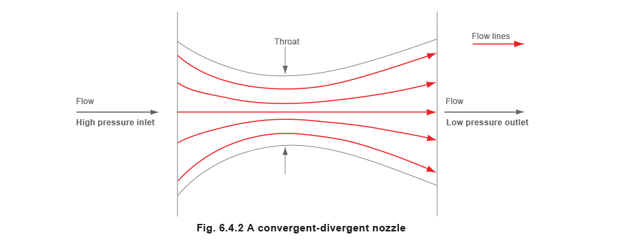
Such a nozzle can be thought of as a type of heat engine, changing heat energy into mechanical (kinetic) energy. It is designed to discharge the required weight of steam with a given pressure drop, and with minimum turbulence and friction losses.
In the convergent section, the steam velocity increases as the pressure falls, though the specific volume of the steam also increases with the lowered pressures. At first, the velocity increases more quickly than the specific volume, and the required flow area through this part of the nozzle becomes less. At a certain point, the specific volume begins to increase more rapidly than does the velocity and the flow area must become greater. At this point, the steam velocity will be sonic and the flow area is at a minimum. The steam pressure at this minimum flow area or ‘throat’ is described as the ‘critical pressure’, and the ratio of this pressure to the initial (absolute) pressure is found to be close to 0.58 when saturated steam is passing.
Critical pressure varies slightly according to the fluid properties, specifically in relation to the ratio of the specific heats cp/cv of the steam (or other gaseous fluid), which is termed the adiabatic index or isentropic exponent of the fluid, often depicted by the symbols ‘n’, ‘k’ or ‘Y symbol - body text.jpg’. With superheated steam the ratio is about 0.55, and for air about 0.53.

Clearly, the mass flow through the throat of a given size is at a maximum at this ‘critical pressure drop’. To achieve a greater flow, either:
Thus, once the critical pressure drop is reached at the throat of the nozzle, or at the ‘vena contracta’ when an orifice is used, further lowering of the downstream pressure cannot increase the mass flow through the device.
If the pressure drop across the whole nozzle is greater than the critical pressure drop, critical pressure will always occur at the throat. The steam will expand after passing the throat such that, if the outlet area has been correctly sized, the required downstream pressure is achieved at the nozzle outlet, and little turbulence is produced as the steam exits the nozzle at high velocity.
Should the nozzle outlet be too big or too small, turbulence will occur at the nozzle outlet, reducing capacity and increasing noise:
- If the nozzle outlet is too small, the steam has not expanded enough, and has to continue expanding outside the nozzle until it reaches the required downstream pressure in the low pressure region.
- If the nozzle outlet is too large, the steam will expand too far in the nozzle and the steam pressure in the nozzle outlet will be lower than the required pressure, causing the steam to recompress outside the outlet in the low pressure region.
The shape of the nozzle (Figure 6.4.3) is gently contoured such that the vena contracta occurs at the nozzle throat. (This is in contrast to a sharp-edged orifice, where a vena contracta occurs downstream of the orifice. The vena contracta effect is discussed in more detail in Module 4.2 ‘Principles of Flowmetering’).
Control valves can be compared to convergent-divergent nozzles, in that each has a high-pressure region (the valve inlet), a convergent area (the inlet between the valve plug and its seat), a throat (the narrowest gap between the valve plug and its seat), a divergent area (the outlet from the valve plug and its seat, and a low-pressure region (the downstream valve body). See Figure 6.4.4.
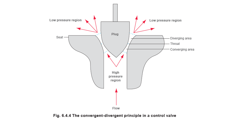
Nozzles and control valves have different purposes. The nozzle is primarily designed to increase steam velocity in order to produce work (perhaps to turn a turbine blade), so the velocity of steam leaving the nozzle is required to remain high.
In contrast, the control valve is a flow restricting or ‘throttling’ device designed to produce a significant pressure drop in the steam. The velocity of steam passing out of a control valve throat will behave in a similar fashion to that of the steam passing out of the throat of a convergent-divergent nozzle; in that it will increase as the steam expands in the diverging area between the plug and seat immediately after the throat. If the pressure drop across the valve is greater than critical pressure drop, the steam velocity will increase to supersonic in this area, as the pressure here is less than that at the throat.
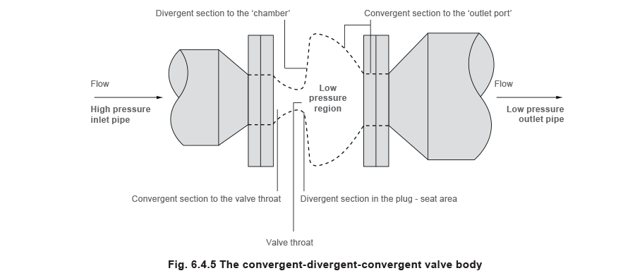
Past this point, the steam passes into the relatively large chamber encased by the valve body (the low pressure region), which is at a higher pressure due to the backpressure imposed by the connecting pipework, causing the velocity and kinetic energy to fall rapidly. In accordance with the steady flow energy equation (SFEE), this increases the steam enthalpy to almost that at the valve entrance port. A slight difference is due to energy lost to friction in passing through the valve.
From this point, the valve body converges to port the steam flow to the valve outlet, and the pressure (and density) approach the pressure (and density) in the downstream pipe. As this pressure stabilises, so does the velocity, relative to the cross sectional area of the valve outlet port.
The relative change in volume through the valve is represented by the dotted lines in the schematic diagram shown in Figure 6.4.5.
When the pressure drop across a valve is greater than critical, noise can be generated by the large instantaneous exchange from kinetic energy to heat energy in the low pressure region, sometimes exacerbated by the presence of supersonic steam.
Valve outlet velocity, noise, erosion, drying and superheating effect
Noise can be an important consideration when sizing control valves, not only because it creates increased sound levels but because its associated vibration can damage valve internals. Special noise-reducing valve trims are available but, sometimes, a less expensive solution is to fit a larger valve body than required. Complicated equations are required to calculate noise emitted from control valves and these are difficult to use manually. It is usually considered that the control valve will produce unacceptable noise if the velocity of dry saturated steam in the control valve outlet is greater than 0.3 Mach. The speed of sound in steam will depend upon the steam temperature and the quality of the steam, but can be calculated from Equation 6.4.2 if the conditions are known (Mach 1 = speed of sound).

A less accurate but useful method to estimate whether noise will be a problem is by calculating the velocity in the valve outlet port. In simplistic terms and for dry saturated steam, if this is greater than 150 m/s, there is a chance that the valve body is too small (even though the valve trim size suits the required capacity). Higher velocities also cause erosion in the downstream valve body, especially if the steam is wet at this point. It is recommended that the maximum exit velocity for wet steam is 40 m/s in the outlet port.
Another result of dropping steam pressure across a control valve is to dry or superheat the steam, depending upon its condition as it enters the valve. Large degrees of superheat are usually unwanted in heating processes, and so it is useful to be able to determine if this will occur. Superheated steam (and dry gas) velocities, however, may be allowed to reach 0.5 Mach in the outlet port; whereas, at the other end of the scale, liquids might be restricted to a maximum outlet velocity of 10 m/s.
Example 6.4.1 The valve outlet velocity and drying/superheating effect
A control valve is supplied with dry saturated steam from a separator at 12 bar g and used to drop steam pressure to 4 bar g at full load. The full load flowrate is 1300 kg/h requiring a Kvr of 8.3. A DN25 (1”) valve is initially considered for selection, which has a Kvs of 10 and a valve outlet area of 0.000 49 m2. What is the steam velocity in the valve outlet?
Determine the state of the steam in the valve outlet at 4 bar g.
The degree of drying and superheating can be calculated from the following procedure:
From steam tables, total heat (hg) in the upsteam dry saturated steam at 12 bar g = 2 787 kJ/kg.
As the supply steam is in a dry saturated state, the steam will certainly be superheated after it passes through the valve; therefore the superheated steam table should be used to quantify its properties.
Using the Spirax Sarco website steam tables, it is possible to calculate the condition of the downstream steam at 4 bar g by selecting ‘Superheated steam’ and entering a pressure of ‘4 bar g’ and a total heat (h) of 2 787 kJ/kg.
By entering these values, the steam table returns the result of superheated steam at 4 bar g with 16.9 degrees of superheat (442 K). (Further details on how to determine the downstream state are given in Module 2.3 ‘Superheated steam’.
Specific volume of superheated steam, 4 bar g, 442 K is 0.391 8 m3 / kg (from the steam table).

It is necessary to see if this velocity is less than 0.5 Mach, the limit placed on valve outlet velocities for superheated steam.
The speed of sound (Mach 1) can be calculated from Equation 6.4.2.

A value of 1.3 is chosen for the isentropic exponent ‘γ’ due to the steam in the valve outlet being superheated.
R is the gas constant for steam 0.461 5 kJ/kg
T is the absolute temperature of 442 K
Therefore the speed of sound in the valve outlet:

As the steam is superheated in the valve outlet, the criterion of 0.5 Mach is used to determine whether the valve will be noisy.
0.5 x 515 = 257.5 m/s
As the expected velocity is 289 m/s and above the limit of 257.5 m/s, the DN25 valve would not be suitable for this application if noise is an issue.
Consider the next largest valve, a DN32 (but with a 25 mm trim). The outlet area of this valve is 0.000 8 m2 (see Table 6.4.1).

The DN32 bodied valve will be suitable because the outlet velocity is less than 0.5 Mach allowed for superheated steam.
The same procedure can be used to determine the conditions of the downstream steam for other upstream conditions. For instance, if the upstream steam is known to be wet, the downstream condition might be wet, dry saturated or superheated, depending on the pressure drop. The allowable outlet velocity will depend on the downstream steam condition as previously outlined in this section, and observed in Example 6.4.2.
Erosion
Another problem is the possibility of erosion in the valve body caused by excessive velocity in the valve outlet. In Example 6.4.1, due to the drying and superheating effect of the pressure drop from 12 bar g to 4 bar g, the steam is in a dry gaseous state containing absolutely no moisture, and erosion should not be an issue.
Simplistically, if it can be guaranteed that the steam leaving a control valve is superheated, then 250 m/s is an appropriate limit to place on the outlet velocity.
Sometimes, when saturated steam is supplied to a control valve, it will be carrying a certain amount of water and the steam may be, for example, 97% or 98% dry. If it has just passed through a properly designed separator it will be close to 100% dry, as in Example 6.4.1.
With anything more than a small pressure drop and wet steam, the steam will probably be dried to saturation point or even slightly superheated.
If the supply steam is dry and/or the valve encounters quite a large pressure drop, (as in Example 6.4.1), the steam will be more superheated.
Equations for sizing control valves
Control valves are not as efficient as nozzles in changing heat into kinetic energy. The path taken by steam through the valve inlet, the throat and into the valve outlet is relatively tortuous.
In a control valve a great deal more energy is lost to friction than in a nozzle, and, because...
• The outlet area of the valve body is unlikely to match the downstream pressure condition.
• The relationship between the plug position and the seat is continually changing.
... turbulence is always likely to be present in the valve outlet.
It seems that control valves of differing types may appear to reach critical flow conditions at pressure drops other than those quoted above for nozzles. Restricted flow passages through the seat of a valve and on the downstream side of the throat may mean that maximum flowrates may only be reached with somewhat greater pressure drops. A ball valve or butterfly valve may be so shaped that some pressure recovery is achieved downstream of the throat, so that maximum flow conditions are reached with an overall pressure drop rather less than expected.
Complicated valve sizing equations can be used to take these and other criteria into consideration, and more than one standard exists incorporating such equations.
One such standard is IEC 60534. Unfortunately, the calculations are so complicated, they can only be used by computer software; manual calculation would be tedious and slow.
Nevertheless, when sizing a control valve for a critical process application, such software is indispensable. For example, IEC 60534 is designed to calculate other symptoms such as the noise levels generated by control valves, which are subjected to high pressure drops. Control valve manufacturers will usually have computer sizing and selection software complementing their own range of valves.
However, a simple steam valve sizing equation, such as that shown in Equation 3.21.2 for saturated steam, is perfectly adequate for the vast majority of steam applications with globe valves.
Also, if consideration is given to critical pressure occurring at 58% of the upstream absolute pressure, a globe valve is unlikely to be undersized.
For simplicity, the rest of this Module assumes critical pressure for saturated steam occurs at 58% of the upstream absolute pressure.
For example, if the pressure upstream of a control valve is 10 bar a, the maximum flowrate through the valve occurs when the downstream pressure is:
10 bar a x 58% = 5.8 bar a
Equally, critical pressure drop is 42% of the upstream pressure, that is, a pressure drop ratio of 0.42. As shown in the previous text, once this downstream pressure is reached, any further increase in pressure drop does not cause an increase in mass flowrate.
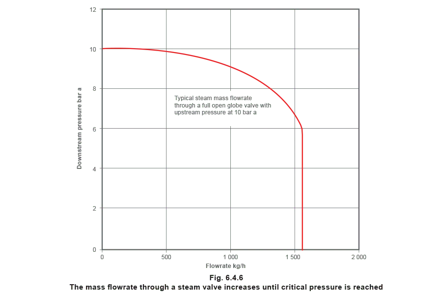
This effect can be observed in Figure 6.4.6 showing how, in the case of a globe valve, the flowrate increases with falling downstream pressure until critical pressure drop is achieved.
Sizing a control valve for a steam heat exchanger is a compromise between:
- A smaller pressure drop that will minimise the size (and perhaps the cost) of the heat exchanger.
- A larger pressure drop that allows the valve to apply effective and accurate control over the pressure and flowrate for most of its travel.
If the pressure drop is less than 10% at full load, three problems can occur:
Simple sizing routine for globe valves in steam service
The flow and expansion of steam through a control valve is a complex process. There are a variety of very complex sizing formulae available, but a pragmatic approach, based on the ‘best fit’ of a mathematical curve to empirical results, is shown in Equation 3.21.2 for globe valves throttling saturated steam. The advantage of this relatively simple formula is that it can be used with the aid of a simple calculator. It assumes that critical pressure drop occurs at 58% of the upstream pressure.

Note: If Equation 3.21.2 is used when P2 is less than the critical pressure, then the term within the bracket (0.42 - curly-x - body text.jpg) becomes negative. This is then taken as zero and the function within the square root sign becomes unity, and the equation is simplified as shown in Equation 6.4.3.

Alternatively, valve-sizing or Kv charts can be used.
Terminology
Normally the full lift value of the valve will be stated using the term Kvs, thus:
Kvr = Actual value required for an application
Kvs = Full lift capacity stated for a particular valve
Manufacturers give the maximum lift Kvs values for their range of valves. Hence the Kv value is not only used for sizing valves but also as a means of comparing the capacity of alternative valve types and makes. Comparing two DN15 valves from different sources shows that valve ‘A’ has a Kvs of 10 and valve ‘B’ a Kvs of 8. Valve ‘A’ will give a higher flowrate for the same pressure drop.
Bringing together the information for steam valve sizing
Certain minimum information is required to determine the correct valve size:
• The pressure of the steam supply must be known.
• The steam pressure in the heat exchanger to meet the maximum heat load must be known.
The difference between the above criteria defines the differential pressure across the valve at its full load condition.
• The heat output of the equipment must be known, along with the enthalpy of evaporation (hfg) at the working pressure in the heat exchanger. These factors are required to determine the steam mass flowrate.
Example 6.4.2
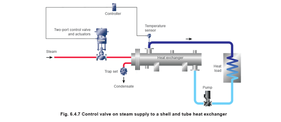
A control valve is required for the application shown in Figure 6.4.7.
The shell and tube heat exchanger manufacturer specifies that a steam pressure of 5 bar absolute is required in the tube bundle to satisfy a process demand of 500 kW.
Wet steam, at dryness 0.96 and 10 bar a, is available upstream of the control valve. Enthalpy of evaporation (hfg) at 5 bar a is 2 108.23 kJ/kg.
Determine the steam flowrate
First, it is necessary to determine the steam state for the downstream condition of 5 bar a. By entering wet steam at 10 bar a, and 0.96 dryness into the Spirax Sarco website wet steam table, it can be seen that the total heat (hg) held in the 10 bar wet steam is 2 697.15 kJ/kg.
The heat exchanger design pressure is 5 bar a, and the total heat in dry saturated steam at this pressure is 2 748.65 kJ/kg (from the steam table).
The total heat in the 10 bar steam (due to its ‘wetness’), is less than the total heat in saturated steam at 5 bar, and so the lower pressure steam will not contain enough heat to be totally dry. The dryness fraction of the lower pressure steam is the quotient of the two total heat figures.
Dryness fraction of the 5 bar a steam = 2 697.15/2 748.65
= 0.98
The energy available for heat transfer at 5 bar a is 0.98 x hfg at 5 bar a
= 0.98 x 2108.23 kJ/kg
= 2 066 kJ/kg
The steam flowrate can now be determined from Equation 2.8.1, where hfg is the enthalpy of evaporation available after accounting for wet steam.

Determine the pressure drop ratio (χ) at full load

Determine the required Kvr
The pressure drop ratio at full load is larger than 0.42, so critical conditions apply and Equation 6.4.3 may be used to find the required Kvr.
A DN25 control valve with a Kvs of 10 is initially selected. A calculation can now be carried out to determine if noise is an issue with this sized valve passing wet steam in the valve outlet.
The speed of sound in the valve outlet:

As this outlet velocity is higher than 40 m/s, the DN25 control valve might:
The DN25 control valve will therefore be unsuitable for this application where wet steam passes through the valve outlet.
One solution to this problem is to fit a larger bodied valve with the same Kvs of 10 to reduce the wet steam outlet velocity.

Consider Table 6.4.1 to determine the minimum sized control valve with an outlet area greater than 0.002 22 m2.
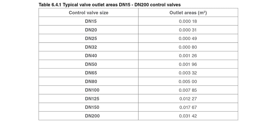
It can be seen from Table 6.4.1 that the smallest valve required to satisfy the maximum outlet velocity of 40 m/s for wet steam is a DN65 valve, having an outlet area of 0.003 32 m2.
Therefore, due to wet steam passing through the valve outlet, the size of the control valve would increase from, in this instance a DN25 (1") to DN65 (2½").
A better solution might be to fit a separator before the control valve. This will allow the smaller DN25 control valve to be used, and is preferred because:
- It will give better regulation as it is more appropriately sized to handle changes in the steam load.
- It will ensure dry steam passes through the control valve, thereby reducing the propensity for erosion at the valve seat and valve outlet.
- It will ensure optimal performance of the heat exchanger, as the heating surface is not thermally insulated by moisture from wet steam.
- The cost of the smaller valve and its actuator plus separator will probably be the same as the larger valve with a larger actuator.
Sizing on an arbitrary pressure drop
If the apparatus working pressure is not known, it is sometimes possible to compromise.
It should be stressed that this method should only be used as a last resort, and that every effort should be made to determine the working pressures and flowrate.
Under these circumstances, it is suggested that the control valve be selected using a pressure drop of 10% to 20% of the upstream pressure. In this way, the selected control valve will more than likely be oversized.
To help this situation, an equal percentage valve will give better operational performance than a linear valve (this is discussed in more detail in Module 6.5 ‘Control valve characteristics’.
Sizing on an arbitrary pressure drop is not recommended for critical applications.
The higher the pressure drop the better?
It is usually better to size a steam valve with critical pressure drop occurring across the control valve at maximum load. This helps to reduce the size and cost of the control valve.
However, the application conditions may not allow this.
For example, if the heat exchanger working pressure is 4.5 bar a, and the maximum available steam pressure is only 5 bar a, the valve can only be sized on a 10% pressure drop ([5 – 4.5]/5) = 0.1. In this situation, sizing on critical pressure drop would have unduly reduced the size of the control valve, and the heat exchanger would be starved of steam.
If it is impossible to increase the steam supply pressure, one solution is to install a larger heat exchanger operating at a lower pressure. In this way, the pressure drop will increase across the control valve.
This could result in a smaller valve but, unfortunately, a larger heat exchanger, because the heat exchanger operating pressure (and temperature) is now lower.
However, a larger heat exchanger working at a lower pressure brings some advantages:
- There is less tendency for the heating surfaces to scale and foul as the required steam temperature is lower.
- Less flash steam is produced in the condensate system leading to less backpressure in the condensate return pipework.
It is important to balance the cost of the valve and heat exchanger, the ability of the valve to control properly, and the effects on the rest of the system, as explained previously.
On steam systems, equal percentage valves will usually be a better choice than linear valves, as low pressure drops will have less effect on their operating performance.
Types of steam heated heat exchangers
This subject is outside the scope of this Module, but it is useful to have a brief look at the two main types of heat exchanger used for steam heating and process applications.
The shell and tube heat exchanger
Traditionally, the shell-and-tube heat exchanger has been used for many steam heating and process applications across a broad spectrum of industries. It is robust and often ‘over-engineered’ for the job. It tends to have an inherently high mass and large thermal hysteresis, which can make it unwieldy for certain critical applications.
Shell-and-tube heat exchangers are often greatly oversized on initial installation, mainly because of large fouling factors applied to the calculation. They tend to have low steam velocity in the steam tube, which reduces:
• Turbulence.
• The sheer stress between the flowing steam and the tube wall.
• Heat transfer.
Low sheer stress also tends not to clean the tube surfaces; hence high fouling factors are usually applied at the design stage leading to oversizing. Due to oversizing, the actual steam pressure after installation is often much less than predicted. If this is not anticipated, the steam trap might not be correctly sized and the steam tubes might flood with condensate, causing erratic control and poor performance.
The plate (and frame) heat exchanger
Plate heat exchangers are a useful alternative; being relatively small and light, they have a small mass and are extremely quick to respond to changes in heat load.
When properly designed, they tend not to foul, but if they do, they are easily disassembled, cleaned and recommissioned. Compared to shell-and-tube exchangers, they can operate at lower pressures for the same duty, but because of their high heat transfer characteristics, and a lower requirement for oversizing, they are still smaller and less expensive than a comparable shell-and-tube exchanger.
Plate heat exchangers (when properly engineered to use steam) are therefore more economically suited to high pressure drops across control valves than their shell-and-tube counterparts. This can give the advantage of smaller and less expensive control valves, whilst minimising the cost of the heat exchanger itself. Generally, it is better to design the system so that the plate exchanger operates with critical pressure drop (or the highest possible pressure drop) across the control valve at full load.
It must be stressed that not all plate heat exchangers are suitable for steam use. It is very easy to buy a heat exchanger designed for liquid use and wrongly assume that it will perform perfectly when heated with steam. Correct selection for steam is not just a matter of pressure/temperature compatibility. Proper expertise is available from bona fide manufacturers, and this should always be sought when steam is the prime energy source.
Steam sizing examples using charts
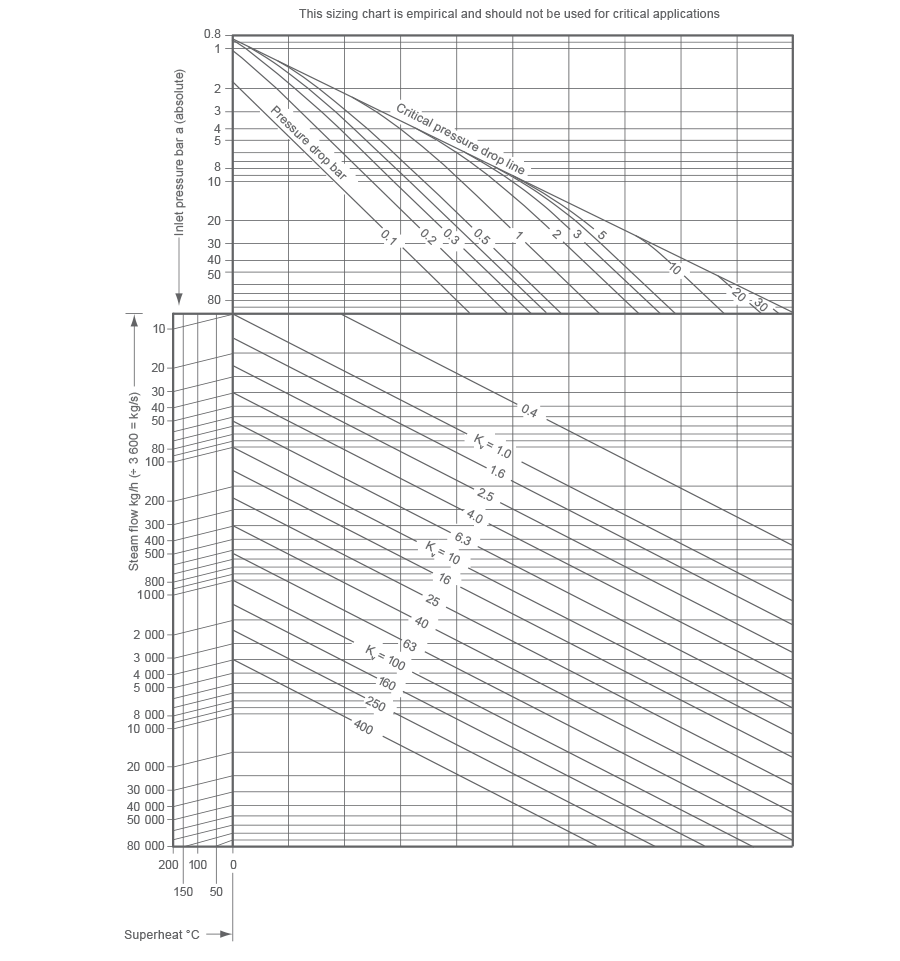
The required ‘flow coefficient’ (Kvr) may be determined in a number of ways, including calculation using Equation 3.21.2 or Equation 6.4.3 or via computer software. An alternative method of simple valve sizing is to use a Kv chart, Figure 6.4.8. A few examples of how these may be used are shown below:
Saturated steam
Example 6.4.3 - Critical pressure drop application
Steam demand of heat exchanger = 800 kg/h
Steam pressure upstream of valve = 9 bar a
Steam pressure required in heat exchanger = 4 bar a
Reference steam Kv chart (Figure 6.4.8)
- Draw a line from 800 kg/h on the steam flow ordinate.
- Draw a horizontal line from 9 bar on the inlet pressure ordinate.
- At the point where this crosses the critical pressure drop line (top right diagonal) draw a vertical line downwards until it intersects the horizontal 800 kg/h line.
- Read the Kv at this crossing point, i.e. Kvr 7.5
Example 6.4.4 - A non critical-pressure-drop application
Steam demand of heat exchanger = 200 kg/h
Steam pressure upstream of valve = 6 bar a
Steam pressure required in heat exchanger = 5 bar a
Reference steam Kv chart (Appendix 1)
As in example 6.4.3, draw a line across from the 200 kg/h steam flow ordinate, and then draw another line from the 6 bar inlet pressure ordinate to the 1 bar pressure drop line.
Drop a vertical line from the resulting intersection point, to meet the 200 kg/h horizontal and read the Kv at this crossing point i.e. Kvr 3.8
Example 6.4.5 - Find the pressure drop (ΔP) across the valve having a known Kvs value
Steam demand of heat exchanger = 3 000 kg/h
Steam pressure upstream of valve = 10 bar a
Kvs of valve to be used = 36
Reference steam Kv chart (Appendix 1)
Draw a horizontal line from 3 000 kg/h to meet at the Kv 36 line. Draw a vertical line upward from this intersection to meet the 10 bar horizontal line.
Read the pressure drop at this crossing point, delta symbol - body text.jpgP 1.6 bar.
Note: In the examples, to convert gauge pressure (bar g) to absolute pressure (bar a) simply add ‘1’ to the gauge pressure, for example, 10 bar g = 11 bar a.

Superheated steam
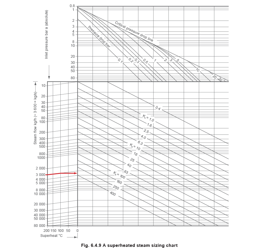
To size a valve for use with superheated steam refer to Example 6.4.6 and the superheated steam chart, Figure 6.4.9.
Example 6.4.6
The following example shows how to use the chart for 100°C of superheat: follow the respective steam flow line on the left to the vertical line which represents 100°C of superheat, then draw a horizontal line across as normal from the resulting intersection. By doing this, the graph introduces a correction factor for the superheat and corrects the Kv value.
Selecting a control valve for steam service
The previous Section covered the procedure for sizing a control valve based on the flowrate it needs to pass, and the pressure drop across the valve. From this data, the Kvs value of the control valve can be obtained. Reference to the appropriate product literature will provide the information needed to select the required valve size.
Control valve selection requires several other factors to be taken into account. The body material must be selected to suit the application. Valves are available in cast iron, SG iron, bronze, steel, stainless steel, and exotic materials for very special applications, for example titanium steel.
The design and material of the control valve must be suitable for the pressure of the system in which it will be fitted. In Europe, most valves have a nominal pressure body rating, stipulated by the letters ‘PN’ which actually means ‘Pression Nominale’. This relates to the maximum pressure (bar gauge) the valve can withstand at a temperature of 120°C. The higher the temperature, the lower the allowable pressure, resulting in a typical pressure/temperature graph as shown in Figure 6.4.10.
It should be noted that the type of material used in manufacturing the control valve plays an important part in the pressure/temperature chart. Typical limiting conditions are:

Typically, the control valve cannot be used if the pressure/temperature conditions are in this area
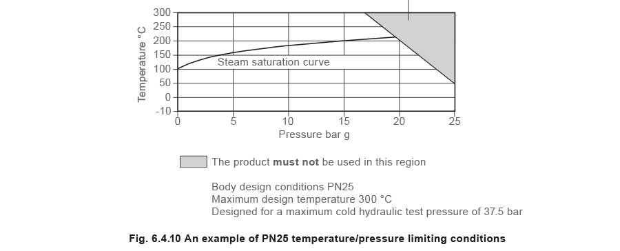
The design thickness and body jointing methods also have an effect. For example, an SG iron valve could have a PN16 rating and may also be available with a slightly different design, with a PN25 rating. Local or national regulations may affect the limits, as may the type of connection which is used.
A checklist of the major factors to be taken into account when selecting a control valve for steam service include:
- Mass flow or volumetric flow to be considered (typically maximum, normal or minimum).
- Flow medium (this may affect the type of material used for the valve body and internals).
- Upstream pressure available at maximum, normal and minimum loads.
- Downstream pressure for maximum, normal and minimum loads.
- Kv value required.
- Pressure drop across the valve at maximum, normal and minimum loads.
- Body size of valve.
- Body material and nominal pressure rating.
- Maximum differential pressure for shut-off.
- Connection required. Which pipe connections are required on the inlet and outlet of the valve? Screwed or flanged connections, and which type of flange, for example, ASME, EN 1092 or DIN?
- Maximum temperature of the medium flowing through the valve.
- Any special requirements, for example, special gland packing variations; hardened valve seat and plug, soft seats for absolutely tight shut-off; and others
Note: Manufacturers restrict the leakage rates of control valves to agreed limits and/or they are sometimes the subject of national standards. Also see point 17.
13. Details of the application control requirements. This is explained in more detail in Module 6.5. Briefly, an application needing on/off control (either fully-open or fully-closed) may require a valve characteristic suited to that purpose, whereas an application calling for continuous control (any degree of opening or closing), might perform better with a different type of valve characteristic.
14. Method of actuation and type of control to be used; for example, self-acting, electric, pneumatic, electropneumatic.
15. Noise levels. It is often a requirement to keep noise below 85 dBA at 1 m from the pipe if people are to work unprotected in the area. Keeping the same size internals but increasing the size of the connections may achieve this. (Many control valves have the option of reduced trim variants, alternatively special noise-reducing trims are available, and/or acoustic lagging can be applied to the valve and pipework. Valves for critical process applications should be sized using computer software utilising the IEC 60534 standard or national equivalent.
16. Pressure drops, sizes of valve body and noise level are related and should be considered. It is good practice to keep the downstream steam velocity in the valve body typically below 150 m/s for saturated steam and 250 m/s for superheated steam. This can be achieved by increasing the valve body size, which will also reduce the velocity in the valve outlet and the likelihood of excess noise. It is possible to consider a saturated steam exit velocity of 150 m/s to 200 m/s if the steam is always guaranteed to be dry saturated at the valve inlet. This is because, under these circumstances, the steam leaving the control valve will be superheated due to the superheating effect of reducing the pressure of dry saturated steam. Please note that these are general figures, different standards will quote different guidelines.
17. Leakage and isolation. Control valves are meant to control flowrate rather than isolate the supply, and are likely to leak slightly when fully shut. Control valves will be manufactured to a standard relating to shut-off tightness. Generally, the better the shut-off, the higher the cost of the valve. For steam control valves, a leakage rate of 0.01% is perfectly adequate for most applications.
18. Turndown. Usually expressed as a ratio of the application maximum expected flow to the minimum controllable flow through a control valve.
19. Rangeability. Usually expressed as a ratio of the valve maximum controllable flow to the minimum controllable flow, between which the characteristics of the control valve are maintained. Typically, a rangeability of 50:1 is acceptable for steam applications.
20. It would be wrong to end this Module on control valves without mentioning cost. The type of valve, its materials of construction, variations in design and special requirements will inevitably result in cost variations. For optimum economy the selected valve should be correct for that application and not over-specified.
Appendix 1 Saturated steam valve sizing chart

Appendix 2 Superheated steam valve sizing chart