Pipeline Ancillaries

Contents
Gauges, Sight Glasses and Vacuum Breakers
These small items of equipment have a variety of important applications throughout steam systems and process equipment. The different types available are studied in this tutorial.
Gauges
Pressure gauges
Pressure gauges should be installed in at least the following situations:
- Upstream of a pressure reducing valve -
To monitor the integrity of the steam supply.
- Downstream of a pressure reducing valve -
To set and monitor the downstream pressure.
Variations in the downstream pressure can lead to reduced plant productivity and product quality. Variations in the downstream pressure may also indicate problems with the pressure reducing valve.
- On blowdown vessels -
A pressure gauge is used to check the vessel pressure during blowdown. This improves safety, since a higher pressure than normal would give an early indication of pipework blockage.
- Flash steam vessels -
To monitor the flash steam pressure.
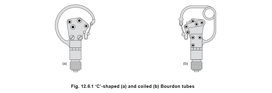
The Bourdon tube pressure gauge is the most commonly used type in steam systems. It consists of a coiled or ‘C’ – shaped tube that is sealed at one end, and open at the other. The open end of the Bourdon tube is exposed to the process fluid, allowing it to flow into the tube. Any increase in pressure causes elastic distortion of the tube, causing it to unwind. The resulting displacement of the closed end of the tube is translated by a series of gears to an angular displacement of the pointer. The pointer position is therefore proportional to the pressure applied at the gauge’s pressure connector. Typically, the maximum deflection of the Bourdon tube corresponds to a pointer angular displacement of 270°.
The tube can be constructed out of a number of different materials, depending on the application; generally, brass or bronze is used for higher pressures, whereas stainless steel is used for lower pressures.
Bourdon tube pressure gauges often have the option of being liquid filled. The area surrounding the Bourdon tube is filled with a transparent liquid, normally glycerine. This protects the internal mechanisms against damage from severe vibration and to keep out ambient corrosives and condensation. This also damps the movement of the pointer making the gauge less susceptible to small transient pressure fluctuations.
As the Bourdon tube may be damaged by high temperatures, it is common practice on steam systems to install the gauge at the end of a syphon tube. The syphon tube is filled with water which transmits the pressure of the working fluid to the Bourdon tube, enabling the gauge to be located some distance from the actual point where the pressure is being measured. The two most common forms of syphon tube are the ‘U’ and ring types. The ring tube is used on horizontal pipelines where there is sufficient space above the pipe, and the ‘U’ type is used when mounting the gauge on a vertical pipeline, or on horizontal pipelines where there is not sufficient space for a ring type siphon.

The Bourdon type pressure gauge is not suitable for use on corrosive liquids or fluids containing suspended solids alone, as these solids may damage the internal elements of the gauge. In such cases, it is necessary to keep the process fluid separate from the Bourdon tube.
This is done by mounting a flexible diaphragm on the inlet to the gauge. The pressure element of the gauge and the space behind the diaphragm form a completely sealed system, which is evacuated and then filled with a suitable filling fluid; in the case of steam this is typically a type of oil. The system pressure causes the diaphragm to deflect, and the pressure is transmitted through the filling fluid to the Bourdon tube.
Diaphragm seals should also be used on ‘clean steam’ applications where no ‘dead space’ is allowed.
In addition to the Bourdon tube pressure gauge, several other types of pressure gauge are available which include; Diaphragm type pressure gauges, Piezoresistive pressure gauges and Temperature gauges.
Diaphragm type pressure gauges
A metal diaphragm is clamped between two flanges, and is exposed to the pressure medium on one side. Pressure exerted by the fluid causes elastic deflection of the diaphragm. The amount of deflection is proportional to the pressure applied on the diaphragm and it causes the linear displacement of a linkage rod attached to the internal side of the diaphragm. The movement of the linkage rod is in turn translated to angular movement of the gauge’s pointer by a series of gears. Thus, the pointer movement is proportional to the pressure exerted on the diaphragm.
The diaphragm also serves to isolate the fluid from the internals of the gauge; therefore, diaphragm type pressure gauges are suitable for use on most fluid types.

Piezoresistive pressure gauges
These pressure gauges consist of a diaphragm made from a ceramic substrate; piezoresistive type strain gauges are bonded to the diaphragm and together with the necessary circuitry, they are integrated on a silicon chip. The diaphragm deflects with changes in pressure, causing a change in the balance of the strain gauge bridge. This is converted by the integrated circuit module to an electronic signal that is proportional to the pressure. The output signal can be fed into a local digital display or further converted into a 4-20 mA signal output for remote transmission.
These gauges are very sensitive and are used where precise measurement of pressure is required. Since they produce an electrical output signal, it is possible to incorporate them into building management systems.
Temperature gauges
Although there are a multitude of different temperature gauges available, five major types are likely to be encountered in steam systems, namely, the bimetallic type, the filled system type, thermistors, thermocouples and resistance temperature devices (RTDs).
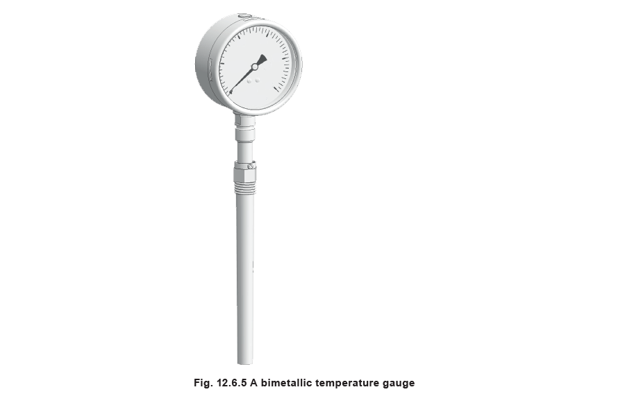
- The bimetallic type temperature gauge -
Consists of a coiled bimetallic element. The gauge is based on the principle of the bimetallic strip, which consists of two metal strips, made from different materials, bonded to each other. The two materials are selected so that they have different thermal coefficients of expansion. The two metals expand by different amounts when heated, and since they cannot move relative to each other, the bimetallic strip bends.

When the temperature of the coiled element rises, it tends to unwind. The degree to which this occurs is indicative of the temperature. A pointer is connected to the coil by a series of linkages, in a similar way to that in the bourdon tube.
Bimetallic gauges tend to be inexpensive, robust and easy to install. They are used where a simple, quick visual indication of temperature is required.
• Other methods of temperature measurement -
are dealt with in Module 6.7, Controllers and Sensors. These types of temperature sensors are used when a higher level of accuracy is required in measuring temperature, or when this function is to be automated or incorporated into a building management system.
It is common to place a temperature-measuring probe into a pocket when installed into an item of plant. This enables the sensor to be removed from pipework or equipment without disturbing the integrity of the system. A heat conducting paste is used in the pocket to provide good heat transfer qualities.
One area of concern when installing a temperature-measuring device is ensuring that it takes a representative reading. It is common, particularly in liquid containing vessels, for there to be some kind of thermal layering of the fluid, and measuring the temperature of the vessels at different levels may produce different results.
Common applications of temperature-measuring devices include boiler feedtanks, measuring product temperatures and measuring the steam temperature after de-superheating.
Sight glasses
A sight glass, or sight flow indicator, provides a method of observing fluid flow in a pipeline. It has two main functions:
- Indication -
Sight glasses are used to indicate if fluid is flowing correctly. They are used to detect blocked valves, strainers, steam traps and other pipeline equipment, as well as to detect if a steam trap is leaking steam.
- Inspection -
Sight glasses can be used to observe the colour of a product at different stages of the production process.
When sight glasses are used to indicate the correct functioning of blast discharge type steam traps, they should be positioned at least 1 m downstream from the trap. For other traps, the sight glass should be positioned immediately after the trap.
Sight glasses do not provide an exact method of monitoring the functioning of steam traps. In practice, a thorough knowledge of the upstream steam system is required and the diagnosis is often subjective, depending on the experience of the observer. For example, depending on the condensate flowrate, pressure and trap discharge pattern, it can be difficult to differentiate if the steam trap is leaking steam or if flash steam is being generated after the steam trap. Sight glasses have generally been replaced by electrical devices such as conductivity sensors, which detect flooding upstream of the steam trap, or leaking traps. These devices do not require steam trap expertise and produce a consistently accurate result.
Sight glasses
The sight glass has a smooth concentric reduction in the inlet connection, which promotes turbulence in the sight glass when fluid is flowing through it. The turbulent flow inside the sight glass permits any fluid to be detected. Sight glasses are available with single, double or multi-viewing windows.

Some sight glasses may be fitted with a light source, these are useful when the sight glass is fitted in an area of low ambient lighting, or where a single window sight glass has to be used, such as in tanks.
Sight check
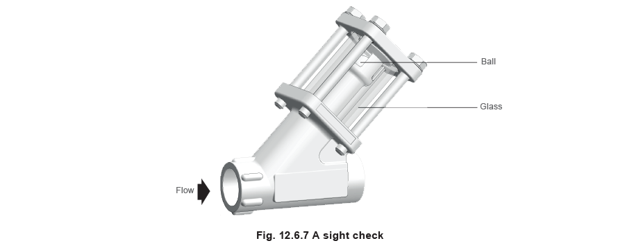
The sight check (see Figure 12.6.7) is a combination of a sight glass and a check valve. A ball in the top of the flow tube is lifted off its seat by the fluid as it flows through the cylindrical window to the outlet connection. When there is reverse flow, the ball is forced back onto its seat on the inlet. The ball movement makes the flow easy to see, as well as providing shut-off on reverse flow.
As with sight glasses, the sight check is used to observe the discharge of steam traps. In the sight check, the position of the ball check indicates whether condensate is flowing. Where condensate rises after the trap, the sight check eliminates the need for a separate check valve, thus simplifying installation. The sight check is particularly useful for commissioning steam traps fitted with a steam lock release (SLR).
Vacuum breakers
Vacuum breakers protect plant and process equipment against vacuum conditions, typically associated with cooling.

The vacuum breaker consists of a spherical stainless steel ball that rests on its seat during normal operating conditions. At the point of vacuum, the valve is lifted off its seat and air is drawn into the system

In some cases, the valve may be spring loaded, which means that the vacuum is only broken when there is a further pressure decrease. This helps to ensure that the shut-off at near vacuum conditions remains bubble tight.
One of the most common applications of a vacuum breaker is on process equipment such as jacketed pans and heat exchangers. When these items are turned off, they still contain a certain amount of steam. The steam condenses as the vessel cools down, and since condensate occupies a much smaller volume than the steam, vacuum conditions are generated. The vacuum can damage the plant and it is therefore necessary to install a vacuum breaker on the steam inlet to such equipment or onto the plant body. The same situation can occur on steam mains and boilers.
A common application of vacuum breakers is on temperature-controlled heat exchangers that are likely to suffer from stall (see Block 13). On smaller heat exchangers draining to atmosphere, the stall condition can be avoided by installing a vacuum breaker on the steam inlet to the heat exchanger. When the vacuum is reached in the steam space, the vacuum breaker opens to allow condensate to drain down to the steam trap.

In general, it is not desirable to introduce air into the steam space, since it acts as a barrier to heat transfer and reduces the effective steam temperature (refer to Module 2.4). This becomes a problem on larger heat exchangers, where it is not advisable to use a vacuum breaker to overcome stall. Furthermore, if the condensate is lifted after the steam trap, for example, into a raised condensate return main, the vacuum breaker cannot assist drainage. In both these cases, it is necessary to use an active method of condensate removal such as a pump-trap (refer to Module 13.8).