Pipeline Ancillaries

Contents
Strainers
Strainers arrest pipeline debris such as scale, rust, jointing compound and weld metal in pipelines, protecting equipment and processes. This tutorial considers the range of strainer and filter types in use and how to size and select them for different applications.
Strainers
As the marketplace becomes increasingly competitive, more emphasis has been placed on reducing plant downtime and maintenance. In steam and condensate systems, damage to plant is frequently caused by pipeline debris such as scale, rust, jointing compound, weld metal and other solids, which may find their way into the pipeline system. Strainers are devices which arrest these solids in flowing liquids or gases, and protect equipment from their harmful effects, thus reducing downtime and maintenance. A strainer should be fitted upstream of every steam trap, flowmeter and control valve.
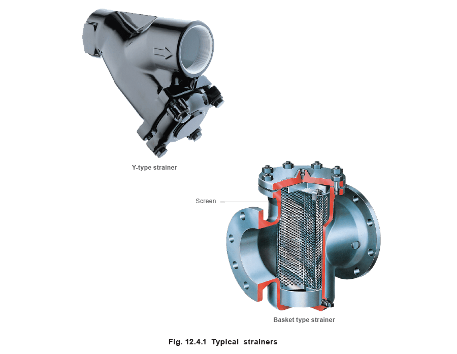
Strainers can be classified into two main types according to their body configuration; namely the Y-type and the basket type. Typical examples of these types of strainers can be seen in Figure 12.4.1.
Y-type Strainers
For steam, a Y-type strainer is the usual standard and is almost universally used. Its body has a compact cylindrical shape that is very strong and can handle high pressures. It is literally a pressure vessel, and it is not uncommon for Y-type strainers to be able to handle pressures of up to 400 bar g. The use of strainers at these pressures is however complicated by the high temperatures associated with steam at this pressure; and subsequently exotic materials such as chrome molybdenum steel have to be used.
Although there are exceptions, size for size, Y-type strainers have a lower dirt holding capacity than basket strainers, which means that they require more frequent cleaning. On steam systems, this is generally not a problem, except where high levels of rust are present, or immediately after commissioning when large amounts of debris can be introduced. On applications where significant amounts of debris are expected, a blowdown valve can usually be fitted in the strainer cap, which enables the strainer to use the pressure of the steam to be cleaned, and without having to shut down the plant.
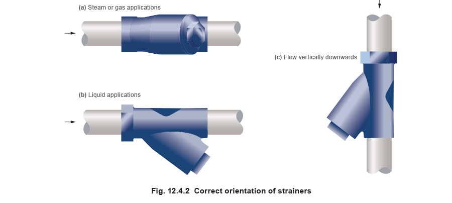
Y-type strainers in horizontal steam or gas lines should be installed so that the pocket is in the horizontal plane (Figure 12.4.2(a)). This stops water collecting in the pocket, helping to prevent water droplets being carried over, which can cause erosion and affect heat transfer processes.
On liquid systems however, the pocket should point vertically downwards (Figure 12.4.2(b)), this ensures that the removed debris is not drawn back into the upstream pipework during low flow conditions.
Although it is advisable to install strainers in horizontal lines, this is not always possible, and they can be installed in vertical pipelines if the flow is downwards, in which case the debris is naturally directed into the pocket (Figure 12.4.2(c)). Installation is not possible with upward flow, as the strainer would have to be installed with the opening of the pocket pointing downwards and the debris would fall back down the pipe.
Straight and angle type strainers
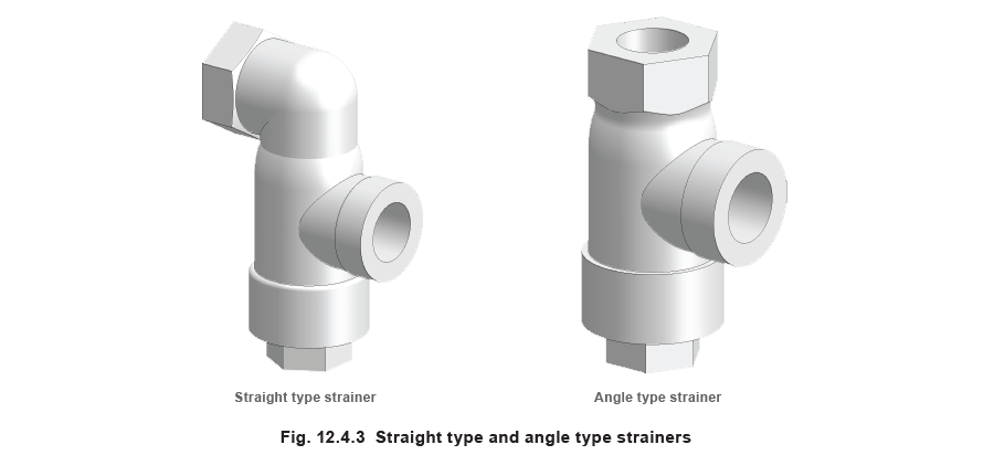
In addition to Y-type strainers, several different body configurations are used in steam systems, namely straight and angle type strainers. These are shown in Figure 12.4.3. These types of strainer function in a similar way to the Y-type strainer and have similar performance. They are used when the geometry of the steam pipework does not suit a Y-type strainer being used.
Basket type strainer units
The basket type or pot type strainer is characterised by a vertically orientated chamber, typically larger than that of a Y-type strainer. Size for size, the pressure drop across a basket strainer is less than that across the Y-type as it has a greater free straining area, which makes the basket type strainer the preferred type for liquid applications. As the dirt holding capacity is also greater than in Y-type strainers, the basket type strainer is also used on larger diameter steam pipelines.
Basket type strainers can only be installed in horizontal pipelines, and for larger, heavier basket strainers, the base of the strainer needs to be supported.
When basket type strainers are used on steam systems, a significant amount of condensate may be formed. Consequently, strainers designed for use in steam systems usually have a drain plug, which can be fitted with a steam trap to remove the condensate.
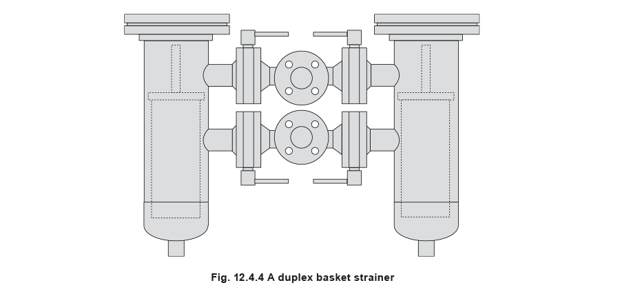
Basket type strainers are commonly found in a duplex arrangement. A second strainer is placed in parallel with the primary strainer, and flow can be diverted through either of the two strainers. This facilitates cleaning of the strainer unit whilst the fluid system is still operating, reducing the downtime for maintenance.
Filters
Whilst strainers remove all visible particles in the steam, it is sometimes necessary to remove smaller particles, for example, in the following applications:
- When there is direct injection of steam into a process, which may cause contamination of the product.
Example: In the food industry, and for the sterilisation of process equipment in the pharmaceutical industry.
- Where dirty steam may cause rejection of a product or process batch due to staining or visible particle retention.
Example: Sterilizers and paper/board machines.
- Where minimal particle emission is required from steam humidifiers.
Example: Humidifiers used in a ‘clean’ environment.
- For the reduction of the steam water content, ensuring a dry, saturated supply.
In such ‘clean steam’ applications, strainers are not suitable and filters must be used. A filter used in a steam system typically consists of a sintered stainless steel filter element. The sintering process produces a fine porous structure in the stainless steel, which removes any particles from fluid passing through it. Filters capable of removing particles as small as 1 μm are available, conforming to the good practice needs of culinary steam.
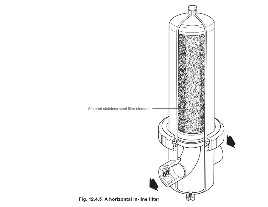
The fine, porous nature of the filter element will create a larger pressure drop across the filter than that associated with the same size strainer; this must be given careful consideration when sizing such filters. In addition, filters are easily damaged by excessive flowrates, and the manufacturer’s specified limits should not be exceeded.
When the filter is used in steam or gas applications, a separator should be fitted upstream of the filter to remove any droplets of condensate held in suspension. In addition to improving the quality of the steam, this will prolong the life of the filter. A Y-type strainer should also be fitted upstream of the filter to remove all larger particles which would otherwise rapidly block the filter, increase the amount of cleaning required and reduce the life of the filter element. By installing pressure gauges either side of the filter, the pressure drop across the filter can be measured, which can then be used to identify when the filter requires cleaning. An alternative to this is to install a pressure switch on the downstream side of the filter. When the downstream pressure decreases below a set level, an alarm light can be switched on in a control room alerting an operator, who can then clean the filter.
Strainer screens
There are two types of screens used in strainers:
- Perforated screens -
These are formed by punching a large number of holes in a flat sheet of the required material using a multiple punch. The perforated sheet is then rolled into a tube and spot welded together.
These are relatively coarse screens and hole sizes typically range from 0.8 mm to 3.2 mm. Consequently, perforated screens are only suitable for removing general pipe debris.
- Mesh screens -
Fine wire is formed into a grid or mesh arrangement. This is then commonly layered over a perforated screen, which acts as a support cage for the mesh.
By using a mesh screen, it is possible to produce much smaller hole sizes than with perforated screens. Hole sizes as small as 0.07 mm are achievable. Subsequently, they are used to remove smaller particles which would otherwise pass through a perforated screen. Mesh screens are usually specified in terms of ‘mesh’; which represents the number of openings per linear inch of screen, measured from the centre line of the wire. Figure 12.4.6 shows a 3 mesh screen.

The corresponding hole size in the mesh screen is determined from knowledge of the wire diameter and the mesh size; it is usually specified by the manufacturer. The maximum particle size that will be allowed to pass through the screen can be determined using geometry. If, for example, a 200 mesh screen is specified and the manufacturer’s specifications stated that the hole size is 0.076 mm, then the maximum particle size that will pass through the screen can be found using Pythagoras’ theorem:
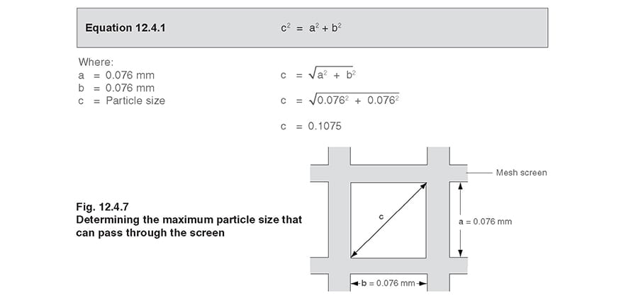
The problem with this dimension is that the screens are two-dimensional and the particle must reach the hole in a certain orientation. Therefore, if a long thin particle reached the strainer ‘face on’, it may be allowed to pass through the screen. However, if it hit the hole ‘side on’ it would be stopped. If this is likely to be a problem, a finer mesh should be used.
The screening area is the area available for removing debris. A larger screening area means that the frequency of blowdown for cleaning the screen is considerably reduced.
The free area is the proportion of the total area of the holes to the total screening area, usually expressed as a percentage. This directly affects the flow capacity of the strainer. The greater the free area (and the coarser the screen), the higher the flow capacity and ultimately the lower the pressure drop across the strainer. As most strainer screens have very large straining and free areas, the pressure drop across the strainer is very low when used on steam or gas systems (see Example 12.4.1). However, in pumped water or viscous fluid systems, the pressure drop can be significant. Strainers should have flow capacities quoted in terms of a capacity index or Kvs value.
Example 12.4.1
A DN40 strainer with a Kvs value of 29, is installed on a 40 mm diameter steam pipe system, which passes 500 kg/h of saturated steam at 8 bar g. What is the pressure drop across the strainer?
Using the empirical formula in Equation 3.21.2:
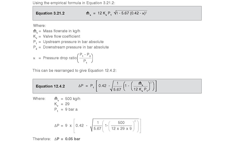
This equates to a pressure drop of just over 0.5%.
The pressure drop across a strainer may be determined either from the Kv value or from a pressure loss diagram. The method for doing this for steam flow is shown in Module 12.2, and for water flow in Module 6.3.
Screens are typically available in a number of different materials; most commonly austenitic stainless steels are used in steam applications, due to their strength and resistance to corrosion. Where the strainer is used with specialised chemicals or in offshore applications, a monel screen should be used.
Strainer options
In addition to standard strainers, there are several other options available.
Magnetic inserts
A magnetic insert may be placed in a basket type strainer in order to remove small iron or steel debris. Small particles of iron or steel may be present in a fluid where there is wear of iron or steel parts. These particles will pass through even the finest mesh screens, and it is necessary to use a magnetic insert. The insert is designed so that all the fluid passes over the magnet at relatively low velocity and the magnetic element is powerful enough to catch and hold all the metal particles present. The magnetic material is usually encased in an inert material such as stainless steel to prevent corrosion.
Self-cleaning strainers
There are number of different types of self-cleaning strainer, which enable the build up of debris on the screen to be removed without shutting down the plant. The cleaning process can be initiated either manually or automatically; furthermore, strainers that are automatically cleaned can usually be set to clean either on a periodic basis, or when the pressure drop across the strainer increases.
- Mechanical type self-cleaning strainers -
use some form of mechanical scraper or brush, which is raked over the screen surface. It dislodges any debris that is trapped in the screen, causing it to fall down into a collection area at the bottom of the strainer.
- Backwashing type strainers -
reverse the direction of flow through the screen. A set of valves is changed over so that water is directed across the screen in the reverse direction and out through a flush valve. The fluid dislodges any debris entrained in the screen and carries it out in the backwash fluid to a waste drain.
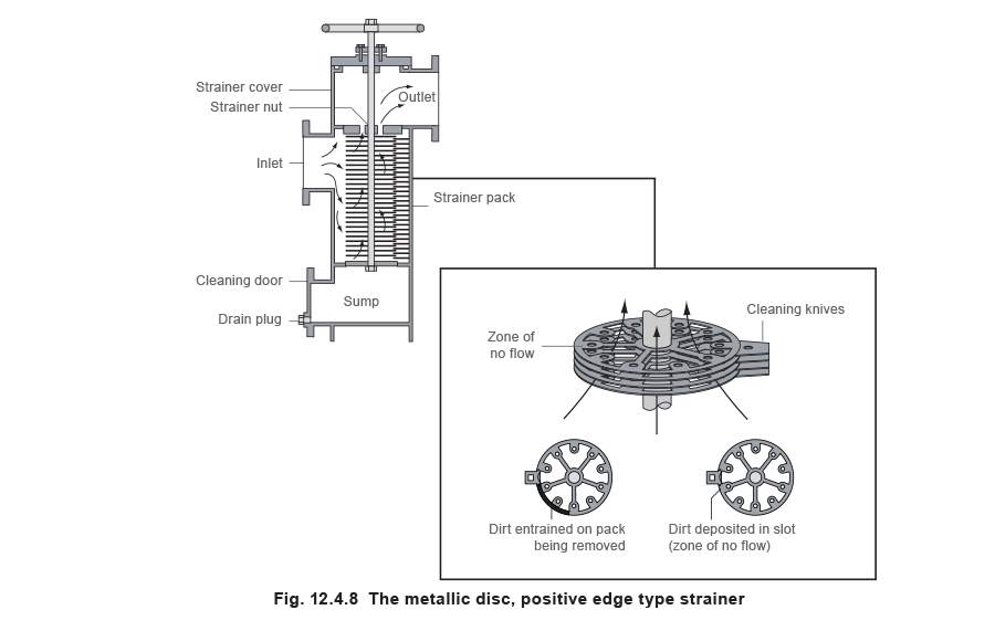
In addition to the mechanical and backwashing type strainers, there are several types of uniquely designed strainer screens. One of the more common types is the metallic disc, positive edge type strainer (see Figure 12.4.8). The straining element is constructed from a pack of circular discs, separated by spacing washers built on a main shaft with tie rods. The thickness of the washers or distance pieces gives the required degree of filtration. The flow direction of the fluid being strained is from the outside of the element to the hollow core, which is formed by the spaces between the main discs. This means that any debris is trapped on the outside surface of the discs.
In order to clean the strainer, the entire strainer pack is rotated by the external handle against a set of stationary cleaning knives interleaved with the main pack. During this rotation, accumulated debris builds up on the leading edge of the cleaning knife, and it is deposited into a solid, vertical groove formed in the outside surface of the strainer element by special packing pieces. As there is no flow through this part of the element there is no force holding the accumulated dirt against the element, and it falls into the sump at the bottom of the strainer.
Temporary strainers
Temporary strainers are designed for protection of equipment and instrumentation during start-up periods. The strainer is usually installed between a set of flanges for an initial period after a new plant has been installed. Installation of a spool piece equal or more than the length of the strainer is recommended for ease of installation or removal.
There are three basic configurations of temporary strainers, namely the conical type, the basket type and the plate type. Standard construction is of perforated screen or single ply heavy wire mesh. Wire mesh liners can be added inside or outside of the strainer for finer straining capabilities. If a wire mesh is used, care must be taken to ensure that the direction of flow is against the wire mesh with the perforated metal as a back-up.
