Safety Valves

Contents
Safety Valve Installation
Important installation advice, including handling, plant conditions, pipework configuration, markings and noise considerations.
Seat tightness
Seat tightness is an important consideration when selecting and installing a safety valve, as not only can it lead to a continuous loss of system fluid, but leakage can also cause deterioration of the sealing faces, which can lead to premature lifting of the valve.
The seat tightness is affected by three main factors; firstly by the characteristics of the safety valve, secondly by the installation of the safety valve and thirdly, by the operation of the safety valve.
Characteristics of the safety valve
For a metal-seated valve to provide an acceptable shut-off, the sealing surfaces need to have a high degree of flatness with a very good surface finish. The disc must articulate on the stem and the stem guide must not cause any undue frictional effects. Typical figures required for an acceptable shut-off for a metal seated valve are 0.5 μm for surface finish and two optical light bands for flatness. In addition, for a reasonable service life, the mating and sealing surfaces must have a high wear resistance.
Unlike ordinary isolation valves, the net closing force acting on the disc is relatively small, due to there being only a small difference between the system pressure acting on the disc and the spring force opposing it.
Resilient or elastomer seals incorporated into the valve discs are often used to improve shut-off, where system conditions permit. It should be noted, however, that a soft seal is often more susceptible to damage than a metal seat.
Safety valve installation
Seat damage can often occur when a valve is first lifted as part of the general plant commissioning procedure, because very often, dirt and debris are present in the system. To ensure that foreign matter does not pass through the valve, the system should be flushed out before the safety valve is installed and the valve must be mounted where dirt, scale and debris cannot collect.
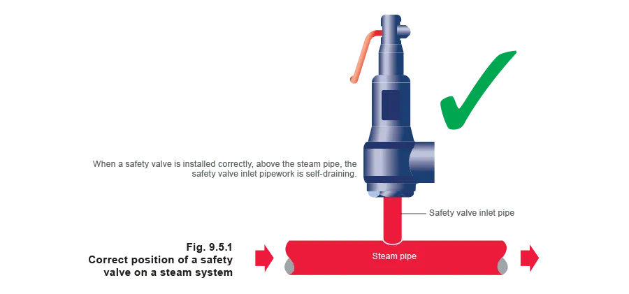
It is also important on steam applications to reduce the propensity for leakage by installing the valve so that condensate cannot collect on the upstream side of the disc. This can be achieved by installing the safety valve above the steam pipe as shown in Figure 9.5.1.
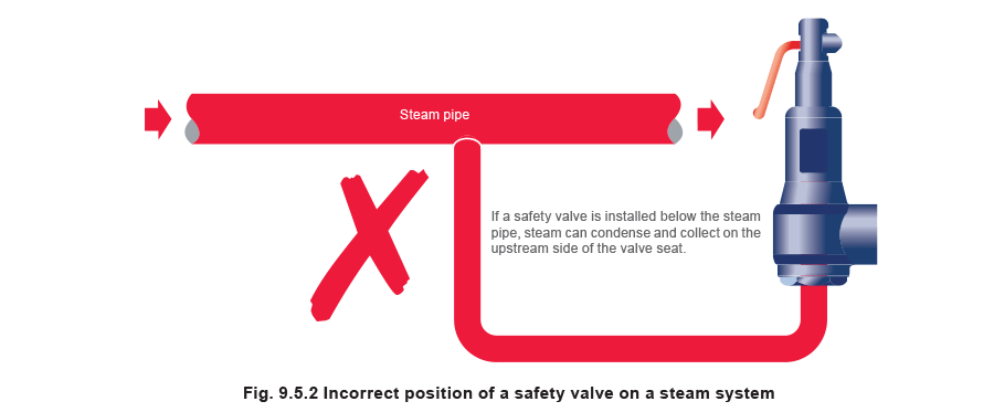
Where safety valves are installed below the pipe, steam will condense, fill the pipe and wet the upstream side of the safety valve seat. This type of installation is not recommended but is shown in Figure 9.5.2 for reference purposes.
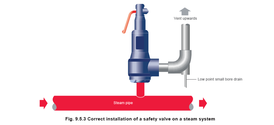
Also, it is essential at all times to ensure that the downstream pipework is well drained so that downstream flooding (which can also encourage corrosion and leakage) cannot occur, as shown in Figure 9.5.3.
Operation of the safety valve
Leakage can also be experienced when there is dirt or scale sitting on the seating face. This usually occurs during the periodic lifting demanded by insurance companies and routine maintenance programs. Further lifting of the lever will generally clear any dirt that may be on the seating face.
The vast majority of safety valve seat leakage problems occur after initial manufacture and test. These problems typically result from damage during transit, and sometimes as a result of misuse and contamination, or because of poor installation.
Most safety valve standards do not include detailed shut-off parameters. For those that do, the requirements and recommended test procedures are usually based on the API 527 standard, which is commonly used throughout the safety valve industry.
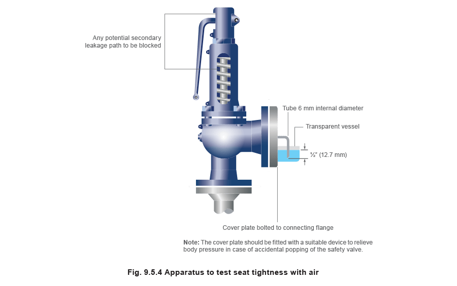
The procedure for testing valves that have been set on air involves blocking all secondary leakage paths, whilst maintaining the valve at 90% of the set pressure on air (see Figure 9.5.4). The outlet of the safety valve is connected to a 6 mm internal diameter pipe, the end of which is held 12.7 mm below the surface of water contained in a suitable, transparent vessel. The number of bubbles discharged from this tube per minute is measured. For the majority of valves set below 70 bar g, the acceptance criteria is 20 bubbles per minute.
For valves set on steam or water, the leakage rate should be assessed using the corresponding setting media. For steam, there must be no visible leakage observed against a black background for one minute after a three-minute stabilisation period. In the case of water, there is a small leakage allowance, dependent on the orifice area, of 10 ml per hour per inch of the nominal inlet diameter.
The above procedure can be time consuming, so it is quite common for manufacturers to employ a test using alternative methods, for example, using accurate flow measuring equipment that is calibrated against the parameters set in API 527.
Under no circumstances should any additional load be applied to the easing lever nor should the valve be gagged in order to increase the seat tightness.
This will affect the operating characteristics and can result in the safety valve failing to lift in overpressure conditions. If there is an unacceptable level of seat leakage, the valve can be refurbished or repaired, but only by authorised personnel, working with the approval of the manufacturer, and using information supplied by the manufacturer.
Commonly supplied spare parts typically include springs, discs and nozzles, resilient seals and gaskets. Many valves have seat rings which are not removable and these can sometimes be re-profiled and re-lapped in the body. However, it is important that the size of seat orifice is maintained exactly in line with the original drawings since this can alter the effective area and, subsequently affect the set pressure.
It is unacceptable for the disc to be lapped directly onto the seat in the body, since a groove will be created on the disc preventing a consistent shut-off after lifting.
In the case of resilient seal valves usually the seal (which is normally an ‘O’ ring or disc) can be changed in the disc assembly.
If Independent Authority Approval is to be maintained then it is mandatory that the repairer is acting as the manufacturer’s approved agent. For ASME approved valves, the repairer must be independently approved by the National Board and is subsequently allowed to apply a ‘VR’ stamp, which indicates a valve has been repaired.
Marking
Safety valve standards are normally very specific about the information which must be carried on the valve. Marking is mandatory on both the shell, usually cast or stamped, and the name-plate, which must be securely attached to the valve. A general summary of the information required is listed below:
On the shell:
- Size designation.
- Material designation of the shell.
- Manufacturer’s name or trademark.
- Direction of flow arrow.
On the identification plate:
- Set pressure (in bar g for European valves and psi g for ASME valves).
- Number of the relevant standard (or relevant ASME stamp).
- Manufacturer’s model type reference.
- Derated coefficient of discharge or certified capacity.
- Flow area.
- Lift and overpressure.
- Date of manufacture or reference number.
National Board approved ASME stamps are applied as follows:
V ASME I approved safety relief valves.
UV ASME VIII approved safety relief valves.
UD ASME VIII approved rupture disc devices.
NV ASME III approved pressure relief valves.
VR Authorised repairer of pressure relief valves.
Table 9.5.1 details the marking system required by TÜV and Table 9.5.2 details the fluid reference letters.

Installation
Safety valves are precision items of safety equipment; they are set to close tolerances and have accurately machined internal parts. They are susceptible to misalignment and damage if mishandled or incorrectly installed.
Valves should be transported upright if possible and they should never be carried or lifted by the easing lever. In addition, the protective plugs and flange protectors should not be removed until actual installation. Care should also be taken during movement of the valve to avoid subjecting it to excessive shock as this can result in considerable internal damage or misalignment.
Inlet pipework
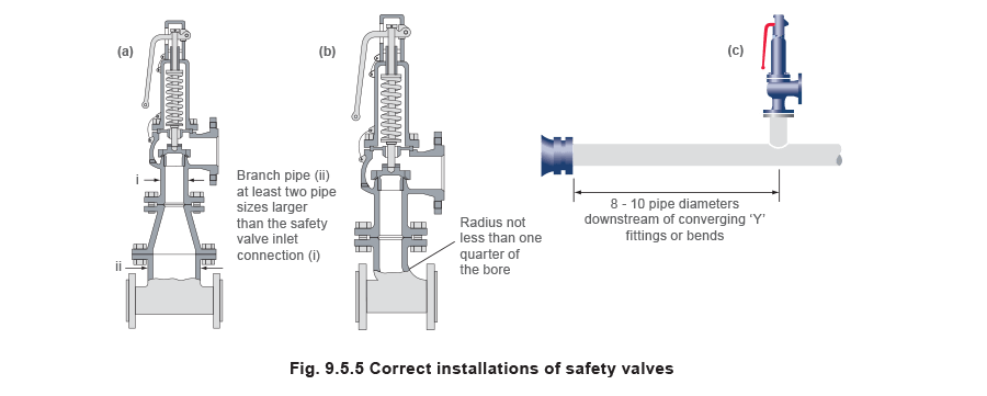
When designing the inlet pipework, one of the main considerations is to ensure that the pressure drop in this pipework is minimised. EN ISO 4126 recommends that the pressure drop be kept below 3% of the set pressure when discharging. Where safety valves are connected using short ‘stub’ connections, inlet pipework must be at least the same size as the safety valve inlet connection. For larger lines or any line incorporating bends or elbows, the branch connection should be at least two pipe sizes larger than the safety valve inlet connection, at which point it is reduced in size to the safety valve inlet size (see Figure 9.5.5a). Excessive pressure loss can lead to ‘chatter’, which may result in reduced capacity and damage to the seating faces and other parts of the valve. In order to reduce the pressure loss in the inlet, the following methods can be adopted:
- Increase the diameter of the pipe. (see Figure 9.5.5 (a)).
- Ensure that any corners are suitably rounded. The standard EN ISO 4126: Part 1 recommends that corners should have a radius of not less than one quarter of the bore (see Figure 9.5.5 (b)).
- Reduce the inlet pipe length.
- Install the valve at least 8 to 10 pipe diameters downstream from any converging or diverging ‘Y’ fitting, or any bend (see Figure 9.5.5 (c)).
- Never install the safety valve branch directly opposite a branch on the lower side of the steam line.
- Avoid take-off branches (such as for other processes) in the inlet piping, as this will increase the pressure drop.
Safety valves should always be installed with the bonnet vertically upwards. Installing the valve in any other orientation can affect the performance characteristics.
The API Recommended Practice 520 guidelines also state that the safety valve should not be installed at the end of a long horizontal pipe that does not normally have flow through it. This can lead to the accumulation of foreign material or condensate in the pipe, which may cause unnecessary damage to the valve, or interfere with its operation.
Outlet pipework
There are two possible types of discharge system – open and closed. An open system discharges directly into the atmosphere whereas a closed system discharges into a manifold along with other safety valves.
It is recommended that discharge pipework should rise for steam and gas systems, whereas for liquids, it should fall. Horizontal pipework should have a downward gradient of at least 1 in 100 away from the valve ensuring that any discharge will be self-draining. It is important to drain any rising discharge pipework. Vertical rises will require separate drainage. Note: all points of system drainage are subject to the same precautions, notably that valve performance must not be affected, and any fluid must be discharged to a safe location.
It is essential to ensure that fluid cannot collect on the downstream side of a safety valve, as this will impair its performance and cause corrosion of the spring and internal parts. Many safety valves are provided with a body drain connection, if this is not used or not provided, then a small bore drain should be fitted in close proximity to the valve outlet (see Figure 9.5.3).
One of the main concerns in closed systems is the pressure drop or built-up backpressure in the discharge system. As mentioned in Module 9.2, this can drastically affect the performance of a safety valve. The EN ISO 4126: Part 1 standard states that the pressure drop should be maintained below 10% of the set pressure. In order to achieve this, the discharge pipe can be sized using Equation 9.5.1.
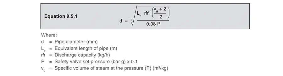
The pressure (P) should be taken as the maximum allowable pressure drop according to the relevant standard. In the case of EN ISO 4126: Part 1, this would be 10% of the set pressure and it is at this pressure vg is taken.
Example 9.5.1
Calculate the nominal diameter of the discharge pipework for a safety valve required to discharge 1 000 kg/h of saturated steam; given that the steam is to be discharged into a vented tank via the pipework, which has an equivalent length of 25 m. The set pressure of the safety valve is 10 bar g and the acceptable backpressure is 10% of the set pressure. (Assume zero pressure drop along the tank vent).
Answer: If the maximum 10% backpressure is allowed, then the gauge pressure at the safety valve outlet will be:
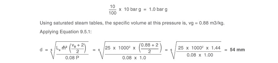
Therefore, the pipework connected to the outlet of the safety valve should have an internal diameter of at least 54 mm. With schedule 40 pipe, this would require a DN65 pipe.
If it is not possible to reduce the backpressure to below 10% of the set pressure, a balanced safety valve should be used.
Balanced safety valves require that their bonnets be vented to atmosphere. In the case of the balanced bellows type, there will be no discharge of the process fluid, so they can be vented directly to the atmosphere. The main design consideration is to ensure that this vent will not become blocked, for example, by foreign material or ice. With the balanced piston type, consideration must be given to the fact that process fluid may be discharged through the bonnet vent. If discharging to a pressurised system, the vent has to be suitably sized, so that no backpressure exists above the piston.
Safety valves that are installed outside of a building for discharge directly into the atmosphere should be covered using a hood. The hood allows the discharge of the fluid, but prevents the build up of dirt and other debris in the discharge pipework, which could affect the backpressure. The hood should also be designed so that it too does not affect the backpressure.
Manifolds
Manifolds must be sized so that in the worst case (i.e. when all the manifold valves are discharging), the pipework is large enough to cope without generating unacceptable levels of backpressure. The volume of the manifold should ideally be increased as each valve outlet enters it, and these connections should enter the manifold at an angle of no greater than 45° to the direction of flow (see Figure 9.5.6). The manifold must also be properly secured and drained where necessary.
For steam applications, it is generally not recommended to use manifolds, but they can be utilised if proper consideration is given to all aspects of the design and installation.

Reaction forces when discharging
In open systems, careful consideration must be given to the effects of the reaction forces generated in the discharge system when the valve lifts. In these systems, there will be significant resultant force acting in the opposite direction to that of discharge. It is important to prevent excessive loads being imposed on the valve or the inlet connection by these reaction forces, as they can cause damage to the inlet pipework. The magnitude of the reaction forces can be calculated using the formula in Equation 9.5.2:
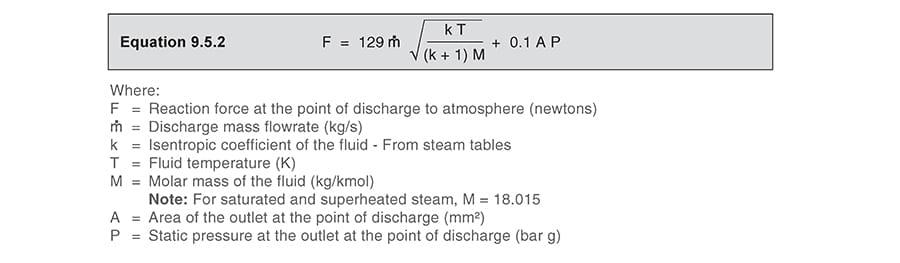
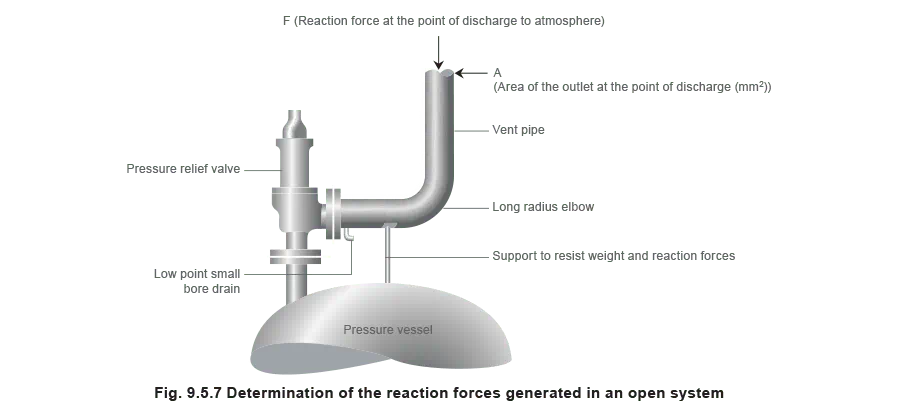
The reaction forces are typically small for safety valves with a nominal diameter of less than 75 mm, but safety valves larger than this usually have mounting flanges for a reaction bar on the body to allow the valve to be secured.
These reaction forces are typically negligible in closed systems, and they can therefore be ignored.
Regardless of the magnitude of the reaction forces, the safety valve itself should never be relied upon to support the discharge pipework itself and a support should be provided to resist the weight of the discharge pipework. This support should be located as close as possible to the centreline of the vent pipe (see Figure 9.5.7).
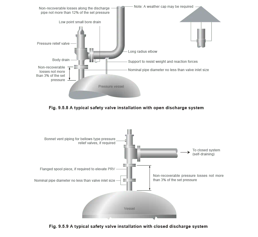
Figures 9.5.8 and 9.5.9 show typical safety valve installations for both open and closed systems.
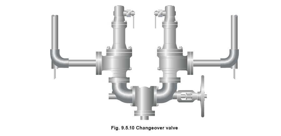
Changeover valves
Changeover valves (see Figure 9.5.10) permit two valves to be mounted side by side, with one in service and one isolated. This means regular maintenance can be carried out without interruption of service or the vessel being protected. Changeover valves are designed in such a way that when they are operated, the pass area is never restricted.
Changeover valves can also be used to connect safety valve outlets so that the discharge pipework does not have to be duplicated. The action of both inlet and outlet changeover valves has to be limited and synchronised for safety reasons. This is usually by means of a chain drive system linking both handwheels.
Consideration must be made to pressure loss caused by the changeover valve when establishing the safety valve inlet pressure drop, which should be limited to 3% of the set pressure.
Noise emission
Although discharge from a safety valve should not occur frequently, should it occur, the noise generated can often be significant. It is therefore necessary to determine the sound level of safety valves to ensure that relevant health and safety regulation levels are not exceeded.
Assuming a sonic flow nozzle discharge, an approximate value of the sound level, LP, in decibels at a flange outlet can be calculated using the formula given in Equation 9.5.3 (Source API 521).
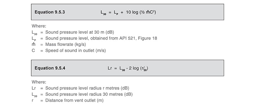
There are several ways to reduce noise level, the simplest being to use larger diameter discharge pipes, or to lag the discharge pipe (however, the valve must not be lagged). It is also permissible for a silencer to be used in extreme cases, in which case any backpressure generated must then be taken into account.