Safety Valves

Contents
Safety Valve Selection
Choosing and commissioning the correct safety valve, including selection considerations, setting, sealing, positioning and the effects of backpressure.
As there is such a wide range of safety valves, there is no difficulty in selecting a safety valve that meets the specific requirements of a given application. Once a suitable type has been selected, it is imperative that the correct relieving pressure and discharge capacity are established, and a suitably sized valve and set pressure is specified.
The selection of a specific type of safety valve is governed by several factors:
- Cost - This is the most obvious consideration when selecting a safety valve for a non-critical application. When making cost comparisons, it is imperative to consider the capacity of the valve as well as the nominal size. As mentioned in the previous module, there can be large variations between models with the same inlet connection but with varying lift characteristics.
- Type of disposal system - Valves with an open bonnet can be used on steam, air or non-toxic gas, if discharge to the atmosphere, other than through the discharge system, is acceptable. A lifting lever is often specified in these applications.
For gas or liquid applications, where escape to the atmosphere is not permitted, a closed bonnet must be specified. In such applications, it is also necessary to use either a closed/gas tight cap or packed lever.
For applications with a significant superimposed backpressure (common in manifolds, typically seen in the process industry) a balancing bellows or piston construction is required.
- Valve construction - A semi-nozzle type construction should be used for non-toxic, non-corrosive type media at moderate pressures, whereas valves with the full nozzle type construction are typically used in the process industry for corrosive media or for extremely high pressures. For corrosive fluids or high temperatures, special materials of construction may also be required.
- Operating characteristics - Performance requirements vary according to application and the valve must be selected accordingly. For steam boilers, a small overpressure is required, usually 3% or 5%. For most other applications, 10% overpressure is required, but according to API 520, for special applications such as fire protection, larger valves with overpressures of 20% are allowed.
For liquids, overpressures of 10% or 25% are common, and blowdown values tend to be up to 20%.
- Approval - For many valve applications, the end user will state the required code or standard for the construction and performance of the valve. This is usually accompanied by a requirement for approval by an independent authority, to guarantee conformance with the required standard.
Setting and sealing
In order to establish the set pressure correctly, the following terms require careful consideration:
- Normal working pressure (NWP) - The operating pressure of the system under full-load conditions.
- Maximum allowable working pressure (MAWP) - Sometimes called the safe working pressure (SWP) or design pressure of the system. This is the maximum pressure existing at normal operating conditions (relative to the maximum operating temperature) of the system.
- Maximum allowable accumulation pressure (MAAP) - The maximum pressure the system is allowed to reach in accordance with the specification of the design standards of the system.
The MAAP is often expressed as a percentage of the MAWP.
For steam using apparatus, the MAAP will often be 10% higher than the MAWP, but this is not always the case. If the MAWP is not readily available, the authority responsible for insuring the apparatus should be contacted. If the MAAP cannot be established, it must not be considered to be higher than the MAWP.
- Set Pressure (P ) - The pressure at which the safety valve starts to lift.
- Relieving pressure (PR) - This is the pressure at which the full capacity of the safety valve is achieved. It is the sum of the set pressure (PS) and the overpressure (PO).
- Overpressure (PO) - The overpressure is the percentage of the set pressure at which the safety valve is designed to operate.
There are two fundamental constraints, which must be taken into account when establishing a safety valve set pressure:
- The set pressure must be low enough to ensure that the relieving pressure never exceeds the maximum allowable accumulation pressure (MAAP) of the system.
- The set pressure must be high enough to ensure that there is sufficient margin above the normal working pressure (NWP) to allow the safety valve to close. However, the set pressure must never be greater than the maximum allowable working pressure (MAWP).
In order to meet the first constraint, it is necessary to consider the relative magnitudes of the percentage overpressure and the percentage MAAP (expressed as a percentage of the MAWP).
There are two possible cases:
- The percentage overpressure of the safety valve is less than or equal to the percentage MAAP of the system - This means that the set pressure can be made to equal the MAWP, as the relieving pressure will always be less than the actual MAAP.
For example, if the safety valve overpressure was 5%, and the MAAP was 10% of the MAWP, the set pressure would be chosen to equal the MAWP. In this case, the relieving pressure (equal to the set pressure + 5% overpressure) would be less than the MAAP, which is acceptable.
Note: that if the percentage MAAP were higher than the percentage overpressure, the set pressure will still be made to equal the MAWP, as increasing it above the MAWP would violate the second constraint.
- The percentage overpressure of the safety valve is greater than the percentage MAAP of the system - In this case, making the set pressure equal to the MAWP will mean that the relieving pressure would be greater than the MAAP, so the set pressure must be lower than the MAWP.
For example, if the safety valve overpressure was 25% and the percentage MAAP was only 10%, making the set pressure equal to the MAWP means that the relieving pressure would be 15% greater than the MAAP. In this instance, the correct set pressure should be 15% below the MAWP.
The following table summarises the determination of the set point based on the first constraint.
Table 9.3.1
Determination of the set pressure using safety valve overpressure and apparatus MAAP
| Apparatus | Safety valve overpressure | |||||
| 5% | 10% | 15% | 20% | 25% | ||
| MAAP |
20% | MAWP | MAWP | MAWP | MAWP | 95% MAWP |
| 15% | MAWP | MAWP | MAWP | 95% MAWP | 90% MAWP | |
| 10% | MAWP | MAWP | 95% MAWP | 90% MAWP | 85% MAWP | |
| 5% | MAWP | 95% MAWP | 90% MAWP | 85% MAWP | 80% MAWP | |
Unless operational considerations dictate otherwise, in order to meet the second constraint, the safety valve set pressure should always be somewhat above the normal working pressure with a margin allowed for the blowdown. A safety valve set just above the normal working pressure can lead to a poor shut-off after any discharge.
When the system operating pressure and safety valve set pressure have to be as close as possible to one another, a 0.1 bar minimum margin between reseat pressure and normal operating pressure is recommended to ensure a tight shut-off. This is called the ‘shut-off margin’. In thiscase, it is important to take into account any variations in the system operating pressure before adding the 0.1 bar margin. Such variations can occur where a safety valve is installed after pressure reducing valves (PRVs) and other control valves, with relatively large proportional bands.
In practically all control systems, there is a certain amount of proportional offset associated with the proportional band (see Block 5, Control Theory, for more information regarding proportional offset). If a self-acting PRV is set under full-load conditions, the control pressure at no-load conditions can be significantly greater than its set pressure. Conversely, if the valve is set under no-load conditions, the full-load pressure will be less than its set pressure.
For example, consider a pilot operated PRV with a maximum proportional band of only 0.2 bar.
With a control pressure of 5.0 bar set under full-load conditions, it would give 5.2 bar under no-load conditions. Alternatively, if the control pressure of 5.0 bar is set under no-load conditions, the same valve would exhibit a control pressure of 4.8 bar under full-load conditions.
When determining the set pressure of the safety valve, if the PRV control pressure is set under no-load conditions, then the proportional offset does not have to be taken into account. However, if the PRV control pressure is set under full-load conditions, it is necessary to consider the increase in downstream pressure as a result of the proportional offset of the PRV (see Example 9.3.1).
The amount of pressure control offset depends on the type of control valve and the pressure controller being used. It is therefore important to determine the proportional band of the upstream control valve as well as how this valve was commissioned.
Example 9.3.1
A safety valve, which is to be installed after a PRV, is required to be set as close as possible to the PRV working pressure. Given the parameters below, determine the most suitable safety valve set pressure:
PRV set pressure: 6.0 bar (set under full-load conditions)
PRV proportional band: 0.3 bar operating above the PRV working pressure
Safety valve blowdown: 10%
Answer:
Since it is necessary to ensure that the safety valve set pressure is as close to the PRV working pressure as possible, the safety valve is chosen so that its blowdown pressure is greater than the PRV working pressure (taking into account the proportional offset), and a 0.1 bar shut-off margin.
Firstly, the effect of the PRV proportional offset needs to be considered as the PRV is being set under load conditions; the normal maximum working pressure that will be encountered is:
6.0 bar + 0.3 bar = 6.3 bar (NWP)
By adding the 0.1 bar shut-off margin, the safety valve set pressure has to be 10% greater than 6.4 bar. For this example, this means that the safety valve’s set pressure has to be:

The set pressure would therefore be chosen as 7.11 bar, provided that this does not exceed the MAWP of the protected system.
Note that if the PRV were set at 6.0 bar under no-load conditions, and with a safety valve 10% blowdown, the safety valve set pressure would be:

Effects of backpressure on set pressure
For a conventional safety valve subject to a constant superimposed backpressure, the set pressure is effectively reduced by an amount equal to the backpressure. In order to compensate for this, the required set pressure must be increased by an amount equal to the backpressure. The cold differential set pressure (the pressure set on the test stand) will therefore be:

For variable superimposed backpressure, the effective set pressure could change as the backpressure varies, and a conventional valve could not be used if the variation were more than 10% to 15% of the set pressure. Instead, a balanced valve would have to be used.
The pressure level relationships for pressure relief valves as shown in the API Recommended Practice 520 is illustrated in Figure 9.3.1.

Setting a safety valve
For most types of safety valve, air or gas setting is permissible. A specially constructed test stand is usually employed, allowing easy and quick mounting of the safety valve, for adjustment, and subsequent locking and sealing of the valve at the required set pressure.
The most important requirement, in addition to the usual safety considerations is that instrument quality gauges are used and a regular calibration system is in place. All safety valve standards will specify a particular tolerance for the set pressure (which is typically around 3%) and this must be observed. It is also important that the environment is clean, dust free and relatively quiet.
The source of the setting fluid can vary from a compressed air cylinder to an intensifier and accumulator vessel running off an industrial compressed air main. In the latter case, the air must be clean, oil, and water free.
It is worth noting that there is no requirement for any sort of capacity test. The test stand simply enables the required set pressure to be ascertained. Usually this point is established by listening for an audible ‘hiss’ as the set point is reached. When making adjustments it is imperative for both metal seated and soft seated valves that the disc is not allowed to turn on the seat or nozzle, since this can easily cause damage and prevent a good shut-off being achieved. The stem should therefore be gripped whilst the adjuster is turned.
There is a fundamental difference in the allowable setting procedures for ASME I steam boiler valves. In order to maintain the National Board approval and to apply the ‘V’ stamp to the valve body, these valves must be set using steam on a rig capable not only of achieving the desired set pressure but also with sufficient capacity to demonstrate the popping point and reseat point. Thismust be done in accordance with an approved, and controlled, quality procedure. For ASME VIII valves (stamped on the body with ‘UV’), if the setter has a steam setting facility, then these valves must also be set on steam. If not, then gas or air setting is permissible. For liquid applications with ASME VIII valves, the appropriate liquid, usually water, must be used for setting purposes.
In the case of valves equipped with blowdown rings, the set positions will need to be established and the locking pins sealed in accordance with the relevant manufacturer’s recommendations.
Sealing
For valves not claiming any particular standard and with no reference to a standard on the nameplate or supporting literature there is no restriction on who can set the valve. Such valves are normally used to indicate that a certain pressure has been reached, and do not act as a safety device.
For valves that are independently approved by a notified body, to a specific standard, the setting and sealing of the valve is a part of the approval. In this case, the valve must be set by the manufacturer or an approved agent of the manufacturer working in accordance with agreed quality procedures and using equipment approved by the manufacturer or the notified body.
To prevent unauthorised alteration or tampering, most standards require provision to be made for sealing the valve after setting.
The most common method is to use sealing wire to secure the cap to the spring housing and the housing to the body. It may also be used to lock any blowdown adjuster ring pins into position.
The wire is subsequently sealed with a lead seal, which may bear the imprint of the setter’s trademark.

Safety valve positioning
In order to ensure that the maximum allowable accumulation pressure of any system or apparatus protected by a safety valve is never exceeded, careful consideration of the safety valve’s position in the system has to be made. As there is such a wide range of applications, there is no absolute rule as to where the valve should be positioned and therefore, every application needs to be treated separately.
A common steam application for a safety valve is to protect process equipment supplied from a pressure reducing station. Two possible arrangements are shown in Figure 9.3.3.
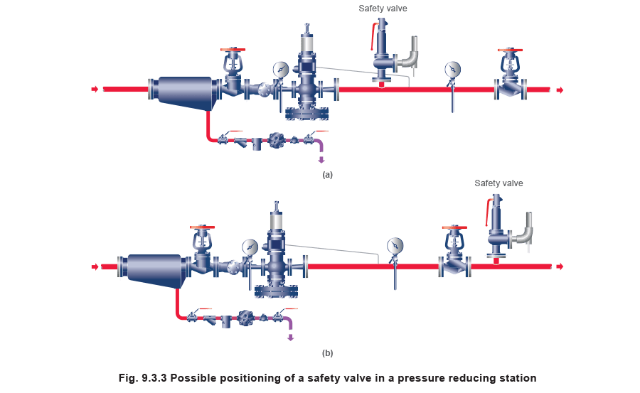
The safety valve can be fitted within the pressure reducing station itself, that is, before the downstream stop valve, as in Figure 9.3.3 (a), or further downstream, nearer the apparatus as in Figure 9.3.3 (b). Fitting the safety valve before the downstream stop valve has the following advantages:
• The safety valve can be tested in-line by shutting down the downstream stop valve without the chance of downstream apparatus being over pressurised, should the safety valve fail under test.
• When the testing is carried out in-line, the safety valve does not have to be removed and bench tested, which is more costly and time consuming.
• When setting the PRV under no-load conditions, the operation of the safety valve can be observed, as this condition is most likely to cause ‘simmer’. If this should occur, the PRV pressure can be adjusted to below the safety valve reseat pressure.
• Any additional take-offs downstream are inherently protected. Only apparatus with a lower MAWP requires additional protection. This can have significant cost benefits.
It is however sometimes practical to fit the safety valve closer to the steam inlet of any apparatus.
Indeed, a separate safety valve may have to be fitted on the inlet to each downstream piece of apparatus, when the PRV supplies several such pieces of apparatus.
The following points can be used as a guide:
• If supplying one piece of apparatus, which has a MAWP pressure less than the PRV supply pressure, the apparatus must be fitted with a safety valve, preferably close-coupled to its steam inlet connection.
• If a PRV is supplying more than one apparatus and the MAWP of any item is less than the PRV supply pressure, either the PRV station must be fitted with a safety valve set at the lowest possible MAWP of the connected apparatus, or each item of affected apparatus must be fitted with a safety valve.
• The safety valve must be located so that the pressure cannot accumulate in the apparatus viaanother route, for example, from a separate steam line or a bypass line.
It could be argued that every installation deserves special consideration when it comes to safety, but the following applications and situations are a little unusual and worth considering:
• Fire - Any pressure vessel should be protected from overpressure in the event of fire. Although a safety valve mounted for operational protection may also offer protection under fire conditions,such cases require special consideration, which is beyond the scope of this text.
• Exothermic applications - These must be fitted with a safety valve close-coupled to the apparatus steam inlet or the body direct. No alternative applies.
• Safety valves used as warning devices - Sometimes, safety valves are fitted to systems as warning devices. They are not required to relieve fault loads but to warn of pressures increasing above normal working pressures for operational reasons only. In these instances, safety valves are set at the warning pressure and only need to be of minimum size. If there is any danger of systems fitted with such a safety valve exceeding their maximum allowable working pressure, they must be protected by additional safety valves in the usual way.
Example 9.3.2
In order to illustrate the importance of the positioning of a safety valve, consider an automatic pump trap (see Block 14) used to remove condensate from a heating vessel. The automatic pump trap (APT), incorporates a mechanical type pump, which uses the motive force of steam to pump the condensate through the return system. The position of the safety valve will depend on the MAWP of the APT and its required motive inlet pressure.
If the MAWP of the APT is more than or equal to that of the vessel, the arrangement shown in Figure 9.3.4 could be used.
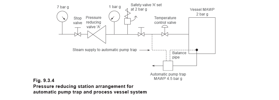
This arrangement is suitable if the pump-trap motive pressure is less than 1.6 bar g (safety valve set pressure of 2 bar g less 0.3 bar blowdown and a 0.1 bar shut-off margin). Since the MAWP of both the APT and the vessel are greater than the safety valve set pressure, a single safety valve would provide suitable protection for the system.
However, if the pump-trap motive pressure had to be greater than 1.6 bar g, the APT supply would have to be taken from the high pressure side of the PRV, and reduced to a more appropriate pressure, but still less than the 4.5 bar g MAWP of the APT. The arrangement shown in Figure 9.3.5 would be suitable in this situation.
Here, two separate PRV stations are used each with its own safety valve. If the APT internals failed and steam at 4 bar g passed through the APT and into the vessel, safety valve ‘A’ would relieve this pressure and protect the vessel. Safety valve ‘B’ would not lift as the pressure in the APT is still acceptable and below its set pressure.
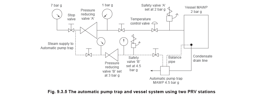
It should be noted that safety valve ‘A’ is positioned on the downstream side of the temperature control valve; this is done for both safety and operational reasons:
- Safety - If the internals of the APT failed, the safety valve would still relieve the pressure in the vessel even if the control valve were shut.
- Operation - There is less chance of safety valve ‘A’ simmering during operation in this position,as the pressure is typically lower after the control valve than before it.
Also, note that if the MAWP of the pump-trap were greater than the pressure upstream of PRV ‘A’, it would be permissible to omit safety valve ‘B’ from the system, but safety valve ‘A’ must be sized to take into account the total fault flow through PRV ‘B’ as well as through PRV ‘A’.
Example 9.3.3
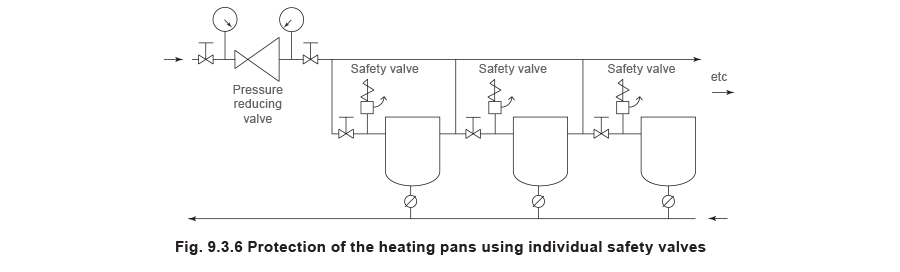
A pharmaceutical factory has twelve jacketed pans on the same production floor, all rated with the same MAWP. Where would the safety valve be positioned?
One solution would be to install a safety valve on the inlet to each pan (Figure 9.3.6). In this instance, each safety valve would have to be sized to pass the entire load, in case the PRV failed open whilst the other eleven pans were shut down.
As all the pans are rated to the same MAWP, it is possible to install a single safety valve after the PRV.
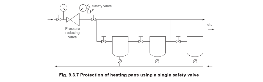
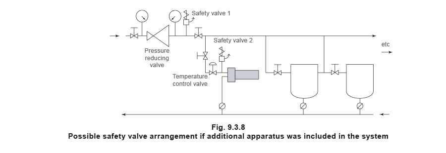
If additional apparatus with a lower MAWP than the pans (for example, a shell and tube heat exchanger) were to be included in the system, it would be necessary to fit an additional safety valve. This safety valve would be set to an appropriate lower set pressure and sized to pass the fault flow through the temperature control valve (see Figure 9.3.8).