Steam Engineering Principles and Heat Transfer

Contents
Heating with Coils and Jackets
Indirect heating of fluids is covered in this tutorial including layouts, control and drainage of coils and jackets, and heat transfer calculations.
Vessels can be heated in a number of different ways. This module will deal with indirect heating.
In these systems, the heat is transferred across a heat transfer surface. Options include:
Submerged steam coils
The use of tank coils is particularly common in marine applications where cargoes of crude oil, edible oils, tallow and molasses are heated in deep tanks. Many of these liquids are difficult to handle at ambient temperatures due to their viscosity. Steam heated coils are used to raise the temperature of these liquids, lowering their viscosity so that they become easier to pump.
Tank coils are also extensively used in electroplating and metal treatment. Electroplating involves passing articles through several process tanks so that metallic coatings can be deposited on to their surfaces. One of the first stages in this process is known as pickling, where materials such as steel and copper are treated by dipping them in tanks of acid or caustic solution to remove any scale or oxide (e.g. rust) which may have formed.
Steam coil sizing
Having determined the energy required (previous Module), and with knowledge of the steam pressure/temperature in the coil, the heat transfer surface may be determined using Equation 2.5.3:

The heat transfer area calculated is equivalent to the surface area of the coil, and will enable an appropriate size and layout to be specified.
Determining the ‘U’ value
To calculate the heat transfer area, a value for the overall heat transfer coefficient, U, must be chosen. This will vary considerably with the thermal and transport properties of both fluids and a range of other conditions.
On the product side of the coil a thermal boundary layer will exist in which there is a temperature gradient between the surface and the bulk fluid. If this temperature difference is relatively large, then the natural convective currents will be significant and the heat transfer coefficient will be high.
Assisted circulation (such as stirring) that will induce forced convection, will also result in higher coefficients. As convection is partially dependent on the bulk motion of the fluid, the viscosity (which varies with temperature) also has an important bearing on the thermal boundary layer.
Additional variations can also occur on the steam side of the coil, especially with long lengths of pipe. The coil inlet may have a high steam velocity and may be relatively free from water.
However, further along the length of the coil the steam velocity may be lower, and the coil may be running partially full of water. In very long coils, such as those sometimes found in seagoing tankers or in large bulk storage tanks, a significant pressure drop occurs along the length of the coil. To achieve the mean coil temperature, an average steam pressure of approximately 75% of the inlet pressure may be used. In extreme cases the average pressure used may be as low as 40% of the inlet pressure.
Another variable is the coil material itself. The thermal conductivity of the coil material may vary considerably. However, overall heat transfer is governed to a large extent by the heat resistant films, and the thermal conductivity of the coil material is not as significant as their combined effect. Table 2.10.1 provides typical overall heat transfer coefficients for various conditions of submerged steam coil application. ‘U’ values for steam pressures between 2 bar g and 6 bar g should be found by interpolation of the data in the table.
Table 2.10.1 Heat emission rates for steam coils submerged in water
| Customary overall heat transfer coefficients |
U (W/m² °C) | |
| Mean steam/water temperature difference around 30 °C |
550 - 1 300 | |
| Mean steam/water temperature difference around 60 °C |
1 000 - 1 700 | |
| Mean steam/water temperature difference around 110 °C |
1 300 - 2 700 | |
| Recommended rates |
U (W/m² °C) | |
| Lower pressure coils | (<2 bar g) with natural circulation of water | 550 |
| Higher pressure coils | (>6 bar g) with natural circulation of water | 1 100 |
| Lower pressure coils | (<2 bar g) with assisted circulation of water | 1 100 |
| Higher pressure coils | (>6 bar g) with assisted circulation of water | 1 700 |
The range of figures shown in Table 2.10.1 demonstrates the difficulty in providing definitive ‘U’ values. Customary figures at the higher end of the scale will apply to installations that are supplied with clean dry steam, small coils and good condensate drainage. The lower end is more applicable to poor quality steam, long coils and poor condensate drainage.
The recommended overall heat transfer coefficients will apply to typical conditions and installations.
These recommended rates are empirically derived, and will generally ensure that a generous safety margin applies to the coil sizing.
In the case of fluids other than water, the heat transfer coefficient will vary even more widely due to the way in which viscosity varies with temperature. However, the values shown in Table 2.10.2 will serve as a guide for some commonly encountered substances, while Table 2.10.3 gives typical surface areas of pipes per metre length.
Table 2.10.2 Heat emission rates for steam coils submerged in miscellaneous liquids
| Medium pressure steam | (2 - 6 bar g) with natural liquid convection | U (W/m² °C) |
| Light oils | 170 | |
| Heavy oils | 80 - 110 | |
| Fats * | 30 - 60 | |
| Medium pressure steam | (2 - 6 bar g) with forced liquid convection | U (W/m² °C) |
| Light oils | (200 sec Redwood at 38 °C) | 550 |
| Medium oils | (1 000 sec Redwood at 38 °C) | 340 |
| Heavy oils | (3 500 sec Redwood at 38 °C) | 170 |
| Molasses ** | (10 000 sec Redwood at 38 °C) | 85 |
| Fats * | (50 000 sec Redwood at 38 °C) | 55 |
* Certain materials such as tallow and margarine are solid at normal temperatures but have quite low viscosities in the molten state.
** Commercial molasses frequently contains water and the viscosity is much lower.
Table 2.10.3 Nominal surface areas of steel pipes per meter length
| Nominal bore (mm) | 15 | 20 | 25 | 32 | 40 | 50 | 65 | 80 | 100 |
| Surface area (m²/m) | 0.067 | 0.085 | 0.106 | 0.134 | 0.152 | 0.189 | 0.239 | 0.279 | 0.358 |
Example 2.10.1
Continuing from Example 2.9.1 determine:
- Part 1. The average steam mass flowrate during start-up. (Mean heat load = 367 kW)
- Part 2. The heat transfer area required.
- Part 3. A recommended coil surface area.
- Part 4. The maximum steam mass flowrate with the recommended heat transfer area.
- Part 5. A recommendation for installation, including coil diameter and layout.
The following additional information has been provided:
- Steam pressure onto the control valve = 2.6 bar g (3.6 bar a).
- A stainless steel steam coil provides heat.
- Heat transfer coefficient from steam/coil/liquid, U = 650 W/m² °C
Part 1 Calculate the average steam mass flowrate during start-up
Steam pressure onto the control valve = 2.6 bar g (3.6 bar a)
Critical pressure drop (CPD) will occur across the control valve during start-up, therefore the minimum steam pressure in the heating coil should be taken as 58% of upstream absolute pressure. An explanation of this is given in Block 5.

Part 2 Calculate the heat transfer area required
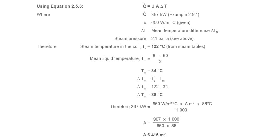
Part 3 A recommendation for coil surface area
Because of the difficulties in providing accurate ‘U’ values, and to allow for future fouling of the heat exchange surface, it is usual to add 10% to the calculated heat transfer area.

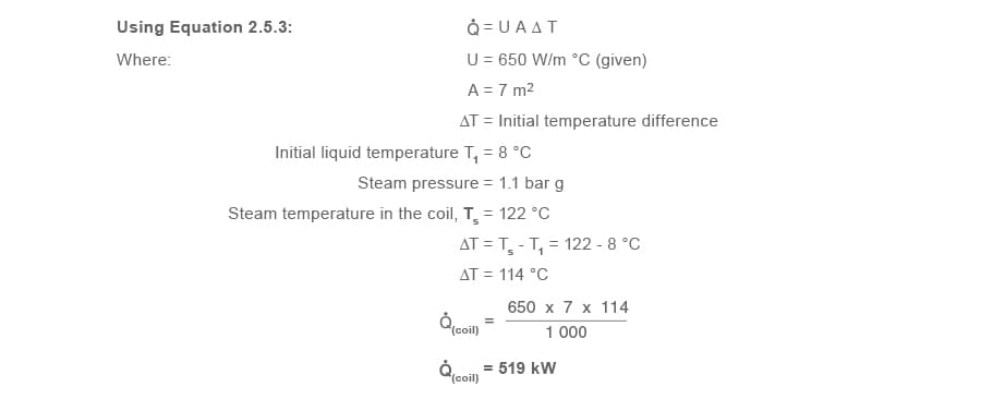
Part 4 The maximum steam mass flowrate with the recommended heat transfer area
Maximum heat transfer (and hence steam demand) will occur when the temperature difference between the steam and the process fluid is at its maximum, and should take into consideration the extra pipe area allowed for fouling.
(a) Consider the maximum heating capacity of the coil Q̇(coil)
(b) Steam flowrate to deliver 519 kW

Part 5 A recommendation for installation, including coil diameter and layout
(a) Determine coil diameter and length

It may be difficult to accommodate this length of large bore heating pipe to install in a 3 m × 3 m tank.
One solution would be to run a bank of parallel pipes between steam and condensate manifolds, set at different heights to encourage condensate to run
to the lower (condensate) manifold. The drain line must fall from the bottom of the condensate manifold down to the steam trap (or pump-trap).
See Figure 2.10.1 for a suggested layout.
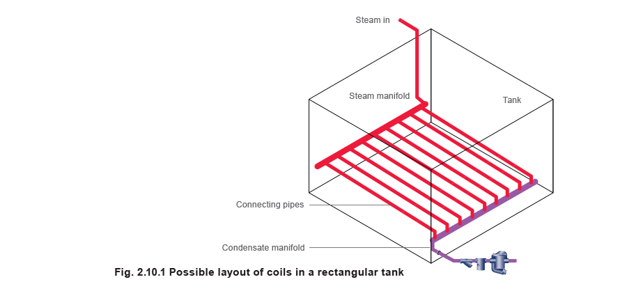
Note the steam supply is situated at one end of its manifold, whilst the trap set is at the other end. This will help steam to flow and push condensate through the coils.
In the application, the steam and condensate headers would each be 2.8 m long. As the condensate manifold is holding condensate, the heat from it will be small compared to the steam manifold and this can be ignored in the calculation.
The steam manifold should be 100 mm diameter as determined by the previous velocity calculation. This will provide a heating area of:
2.8 m x 0.358 m²/m = 1.0 m²
Consequently 7 m² - 1 m² = 6 m² of heat transfer area is still required, and must be provided by the connecting pipes.
Arbitrarily selecting 32 mm pipe as a good compromise between robustness and workability:

Check
It is necessary to confirm the steam velocity through the connecting tubes:
On the basis of proportionality of heat transfer area, the steam header will condense:

Other steam coil layouts
The design and layout of the steam coil will depend on the process fluid being heated. When the process fluid to be heated is a corrosive solution, it is normally recommended that the coil inlet and outlet connections are taken over the lip of the tank, as it is not normally advisable to drill through the corrosion resistant linings of the tank side. This will ensure that there are no weak points in the tank lining, where there is a risk of leakage of corrosive liquids. In these cases the coil itself may also be made of corrosion resistant material such as lead covered steel or copper, or alloys such as titanium.
However, where there is no danger of corrosion, lifts over the tank structure should be avoided, and the steam inlet and outlet connections may be taken through the tank side. The presence of any lift will result in waterlogging of a proportion of the coil length, and possibly waterhammer, noise and leaking pipework.
Steam heating coils should generally have a gradual fall from the inlet to the outlet to ensure that condensate runs toward the outlet and does not collect in the bottom of the coil.
Where a lift is unavoidable, it should be designed to include a seal arrangement at the bottom of the lift and a small bore dip pipe, as shown in Figure 2.10.2.
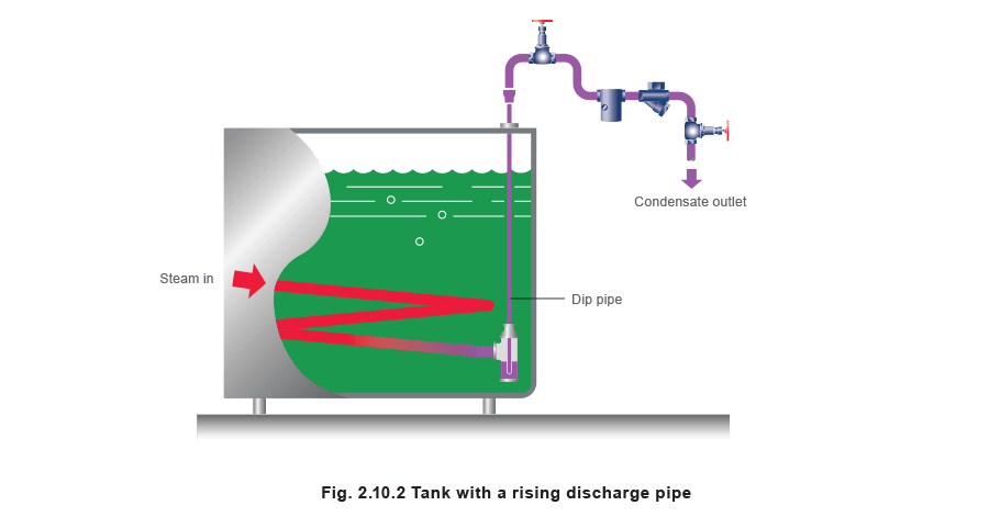
The seal arrangement allows a small amount of condensate to collect to act as a water seal, and prevents the occurrence of steam locking. Without this seal, steam can pass over any condensate collecting in the bottom of the pipe, and close the steam trap at the top of the riser.
The condensate level would then rise and form a temporary water seal, locking the steam between the bottom of the riser and the steam trap. The steam trap remains closed until the locked steam condenses, during which time the coil continues to waterlog.
When the locked steam condenses and the steam trap opens, a slug of water is discharged up the riser. As soon as the water seal is broken, steam will enter the rising pipe and close the trap, while the broken column of water falls back to lie at the bottom of the heating coil.
The small bore dip pipe will only allow a very small volume of steam to become locked in the riser. It enables the water column to be easily maintained without steam bubbling through it, ensuring there is a steady and continuous condensate flow to the outlet.
When the seal is ultimately broken, a smaller volume of water will return to the heating coil than with an unrestricted large bore riser, but as the water seal arrangement requires a smaller volume of condensate to form a water seal, it will immediately re-form.
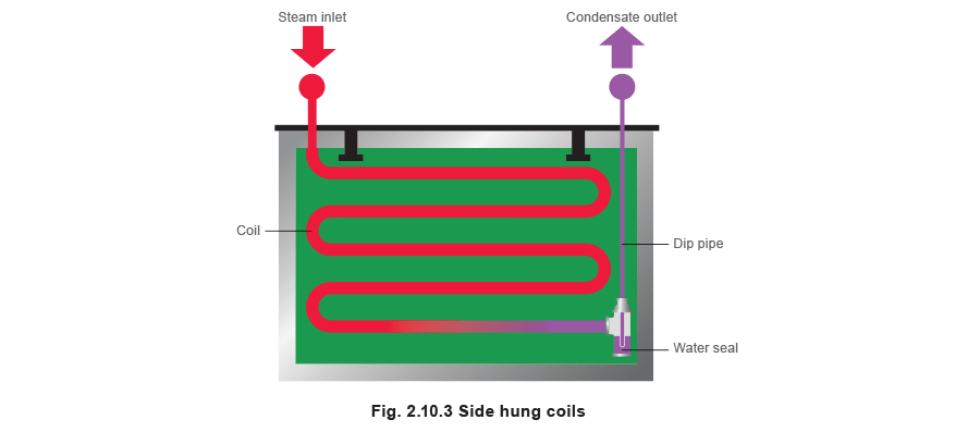
If the process involves articles being dipped into the liquid, it may not be convenient to install the coil at the bottom of the tank - it may be damaged by the objects being immersed in the solution.
Also, during certain processes, heavy deposits will settle at the bottom of the tank and can quickly cover the heating surface, inhibiting heat transfer.
For these reasons side hung coils are often used in the electroplating industry. In such cases serpentine or plate-type coils are arranged down the side of a tank, as shown in Figure 2.10.3. These coils should also have a fall to the bottom with a water seal and a small bore dip-pipe.This arrangement has the advantage that it is often easier to install, and also easier to remove for periodic cleaning if required.
If articles are to be dipped into the tank, it may not be possible to use any sort of agitator to induce forced convection and prevent temperature gradients occurring throughout the tank. Whether bottom or side coils are used, it is essential that they are arranged with adequate coverage so that the heat is distributed evenly throughout the bulk of the liquid.
The diameter of the coil should provide sufficient length of coil for good distribution. A short length of coil with a large diameter may not provide adequate temperature distribution. However a very long continuous length of coil may experience a temperature gradient due to the pressure drop from end to end, resulting in uneven heating of the liquid.
Whilst the next two headings, ‘Sizing the control valve’ and ‘The condensate removal device’ are included in this Module, the new reader should refer to later Blocks and Modules in The Learning Centre for full and comprehensive information, before attempting sizing and selection of equipment.
Control valve arrangement
The control valve set may be either one or two valves in parallel. A single control valve, large enough to cope with the maximum flowrate encountered at start-up, may be unable to control flow accurately at the minimum expected flowrate. This could cause erratic temperature control.
An alternative is to fit two temperature control valves in parallel:
- One valve (running valve) sized to control at the lower flowrate.
- A second valve (starting valve) to pass the difference between the capacity of the first valve, and the maximum flowrate.
The starting valve would have a set-point slightly lower than the running valve, so it would close first, leaving the running valve to control at low loads.
Sizing the control valve
The control valve set (either one valve or two valves in parallel).
The coil has been sized on mean heat transfer values. However, it may be better to size the control valve to supply the maximum (start-up) load. With large coils in tanks, this will help to maintain a degree of steam pressure throughout the length of the coil when the steam is turned on, helping to push condensate through the coil to the steam trapping device. If the control valve were sized on mean values, steam pressure in the coil at start-up will tend to be lower and the coil may flood.
Using one valve
Continuing with Example 2.10.1 the maximum steam load is 850 kg/h and the coil is designed to deliver this at a pressure of 1.1 bar g. A steam valve sizing chart would show that a Kv of about 20 is required to pass 850 kg/h of steam with a pressure of 2.6 bar g at the inlet of the control valve, and Critical Pressure Drop (CPD) across the valve. (Module 6.4 will show how the valve size can be determined by calculation).
A DN40 control valve with a larger Kvs of 25 would therefore need to be selected for the application.
If one valve is to be used, this valve must ensure the maximum heat load is catered for, while maintaining the required steam pressure in the coil to assist the drainage of condensate from it at start-up. However, for reasons previously explained, two valves may be better.
The running load is 52 kW and with the coil running at 1.1 bar g, the running steam load:

The steam valve sizing chart shows a Kv of 2 is required to pass 85 kg/h with 3.6 bar upstream, operating at critical pressure drop.
A DN15 KE type valve (Kvs = 4) and a DN25 piston actuated valve (Kvs = 18.6) operating together will cater for the start-up load. When approaching the control temperature, the larger valve would be set to shut down, allowing the smaller valve to give good control.
The condensate removal device
The selection and sizing of the condensate removal device will be very much influenced by the condensate backpressure. For the purpose of this example, it is assumed the backpressure is atmospheric pressure. The device should be sized so it is able to satisfy both of the following
conditions:
- Pass 850 kg/h of condensate with 1.1 bar g in the coil, i.e. the full-load condition.
- Pass the condensate load when steam pressure in the coil equals the condensate backpressure, i.e. the stall load condition.
If the steam trap is only sized on the first condition, it is possible that it may not pass the stall load (the condition where the product approaches its required temperature and the control valve modulates to reduce steam pressure). The stall load may be considerable. With respect to non-flow type applications such as tanks, this may not be too serious from a thermal viewpoint because the contents of the tank will almost be at the required temperature, and have a huge reservoir of heat.
Any reduction in heat transfer at this part of the heating process may therefore have little immediate effect on the tank contents.
However, condensate will back up into the coil and waterhammer will occur, along with its associated symptoms and mechanical stresses. Tank coils in large circular tanks tend to be of robust construction, and are often able to withstand such stresses. Problems can however occur in rectangular tanks (which tend to be smaller), where vibration in the coil will have more of an effect on the tank structure. Here, the energy dissipated by the waterhammer causes vibration, which can be detrimental to the life of the coil, the tank, and the steam trap, as well as creating unpleasant noise.
With respect to flow-type applications such as plate heat exchangers, a failure to consider the stall condition will usually have serious implications. This is mainly due to the small volume in the heat exchanger.
For heat exchangers, any unwanted reduction in the heating surface area, such as that caused by condensate backing up into the steam space, can affect the flow of heat through the heating surface. This can cause the control system to become erratic and unstable, and processes requiring stable or accurate control can suffer with poor performance.
If heat exchangers are oversized, sufficient heating surface may remain when condensate backs up into the steam space, and reduction of thermal performance may not always occur.
However, with heat exchangers not designed to cope with the effects of waterlogging, this can lead to corrosion of the heating surface, inevitably reducing the service life of the exchanger. Waterlogging can, in some applications, be costly. Consider a waterlogging air heater frost coil. Cold air at 4 °C flowing at 3 m/s can soon freeze condensate locked in the coils, resulting in premature and unwarranted failure. Proper drainage of condensate is essential to maintain the service life of any heat exchanger and air heater.
Steam traps are devices which modulate to allow varying amounts of condensate to drain from applications under varying conditions. Float traps are steam traps designed to modulate and release condensate close to steam temperature, offering maximum plant performance, maximum plant life, and maximum return on plant investment.
When stall conditions occur, and a steam trap cannot be used, an automatic pump-trap or pump and trap in combination will ensure correct condensate drainage at all times, thus maximising the thermal capability and lifetime costs of the plant.
Steam jackets
The most commonly used type of steam jacket consists simply of an outer cylinder surrounding the vessel, as shown in Figure 2.10.4. Steam circulates in the outer jacket, and condenses on the wall of the vessel. Jacketed vessels may also be lagged, or may contain an internal air space surrounding the jacket. This is to ensure that as little steam as possible condenses on the outer jacket wall, and that the heat is transferred inwards to the vessel.
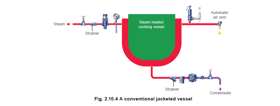
The heat transfer area (the vessel wall surface area), can be calculated in the same manner as with a steam coil, using Equation 2.5.3 and the overall heat transfer coefficients provided in Table 2.10.4.
Although steam jackets may generally be less thermally efficient than submerged coils, due to radiation losses to the surroundings, they do allow space for the vessels to be agitated so that heat transfer is promoted. The U values listed in Table 2.10.4. are for moderate nonproximity agitation.
Commonly the vessel walls are made from stainless steel or glass lined carbon steel. The glass lining will offer an additional corrosion resistant layer. The size of the steam jacket space will depend on the size of the vessel, but typically the width may be between 50 mm and 300 mm.
Table 2.10.4 Overall heat transfer coefficients for steam jackets
| Process fluid or product | Wall material | U (W/m² °C) |
| Water |
Stainless steel | 850 - 1 700 |
| Glass-lined carbon steel | 400 - 570 | |
| Aqueous solution |
Stainless steel | 450 - 1 140 |
| Glass-lined carbon steel | 285 - 480 | |
| Organics |
Stainless steel | 285 - 850 |
| Glass-lined carbon steel | 170 - 400 | |
| Light oil |
Stainless steel | 340 - 910 |
| Glass-lined carbon steel | 230 - 425 | |
| Heavy oil |
Stainless steel | 57 - 285 |
| Glass-lined carbon steel | 57 - 230 |