Steam Engineering Principles and Heat Transfer

Contents
Steam Consumption of Heat Exchangers
Different types of heat exchanger are explained and compared in this tutorial, together with steam consumption calculations and other issues such as the relevance of the starting load.
The term heat exchanger strictly applies to all types of equipment in which heat transfer is promoted from one medium to another. A domestic radiator, where hot water gives up its heat to the ambient air, may be described as a heat exchanger. Similarly, a steam boiler where combustion gases give up their heat to water in order to achieve evaporation, may be described as a fired heat exchanger.
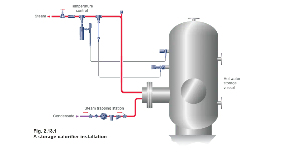
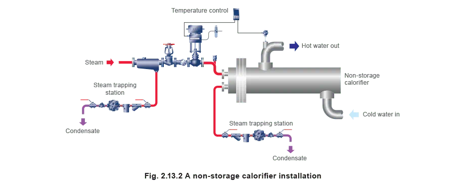
However, the term is often more specifically applied to shell and tube heat exchangers or plate heat exchangers, where a primary fluid such as steam is used to heat a process fluid. A shell and tube heat exchanger used to heat water for space heating (using either steam or water) is often referred to as a non-storage calorifier. (A storage calorifier, as shown in Figure 2.13.1, is constructed differently, it usually consists of a hot water storage vessel with a primary heating coil inside).
Manufacturers often provide a thermal rating for their heat exchangers in kW, and from this the steam consumption may be determined, as for air heater batteries. However, heat exchangers (particularly shell and tube) are frequently too large for the systems which they are required to serve.
A non-storage calorifier (as shown in Figure 2.13.2) will normally be selected from a standard range of sizes, and may often have a much larger capacity than the design figure. For the hot water heating of buildings there may also be certain safety factors included in the heat load calculations.
Plate heat exchangers may also be chosen from a standard range of sizes if the units are brazed or welded. However, there is more flexibility in the sizing of gasketed plate heat exchangers, where plates can often be added or removed to achieve the desired heat transfer area. In many cases, plate heat exchangers are oversized simply to reduce the pressure drop for the secondary fluid.
On existing plant, an indication of actual load may be obtained if the flow and return temperatures and the pumping rate are known. However, it is important to note that throughput as given on the pump maker’s plate will probably relate to a pressure head, which may or may not be present in practice.
Steam consumption calculations for heat exchangers
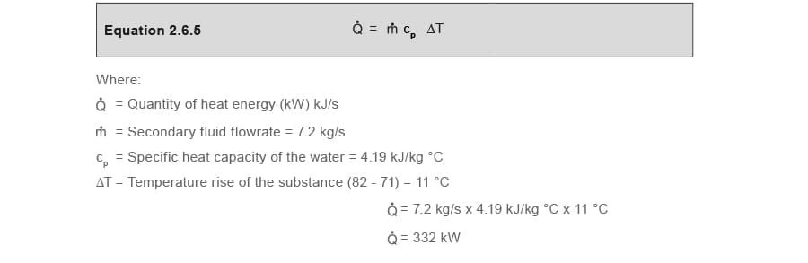
Shell and tube heat exchangers and plate heat exchangers are typical examples of flow type applications. Therefore, when determining the steam consumption for these applications, Equation 2.6.5 should be used.
The start-up load may be ignored if it occurs rarely, or if the time taken to reach full-load output is not too important. Heat exchangers are more often sized on the full running load, with the possible addition of safety factors.
Heat losses are rarely taken into account with these flow type applications, as they are significantly less than the full running load. Shell and tube heat exchangers are usually lagged to prevent heat loss, and to prevent possible injury to personnel. Plate heat exchangers tend to be more compact and have a much smaller surface area exposed to the ambient air, in relation to the size of the unit.
Example 2.13.1
Determine the heat load and steam load of the following non-storage heating calorifier
A heating calorifier is designed to operate at full-load with steam at 2.8 bar g in the primary steam space.
The secondary water flow and return temperatures are 82 °C and 71 °C respectively, at a pumped water rate of 7.2 kg/s.
cp for water = 4.19 kJ/kg °C
Table 2.13.1 Extract from steam tables
| Pressure bar g |
Saturation temperature °C | Enthalpy (energy) in kJ/kg | Specific volume of dry saturated steam m3/kg | ||
| Water hf |
Evaporation hfg |
Steam hg |
|||
| 2 | 134 | 562 | 2 163 | 2 725 | 0.603 |
| 2.8 | 142 | 596 | 2 139 | 2 735 | 0.489 |
| 3 | 144 | 605 | 2 133 | 2 738 | 0.461 |
Part 1 Determine the heat load
The full-load may be calculated using Equation 2.6.5:
Part 2 Determine the steam load
The full-load condensing rate can be determined using the left hand side of the heat balance Equation 2.6.6:
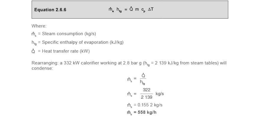
Plate heat exchangers
A plate heat exchanger consists of a series of thin corrugated metal plates between which a number of channels are formed, with the primary and secondary fluids flowing through alternate channels. Heat transfer takes place from the primary fluid steam to the secondary process fluid in adjacent channels across the plate. Figure 2.13.3 shows a schematic representation of a plate heat exchanger.
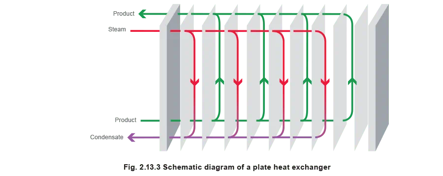
A corrugated pattern of ridges increases the rigidity of the plates and provides greater support against differential pressures. This pattern also creates turbulent flow in the channels, improving heat transfer efficiency, which tends to make the plate heat exchanger more compact than a traditional shell and tube heat exchanger. The promotion of turbulent flow also eliminates the presence of stagnant areas and thus reduces fouling. The plates will usually be coated on the primary side, in order to promote the dropwise condensation of steam.
The steam heat exchanger market was dominated in the past by the shell and tube heat exchanger, whilst plate heat exchangers have often been favoured in the food processing industry and used water heating. However, recent design advances mean that plate heat exchangers are now equally suited to steam heating applications.
A plate heat exchanger may permit both the condensing and sub-cooling of condensate within a single unit. If the condensate is drained to an atmospheric receiver, by reducing the condensate temperature, the amount of flash steam lost to the atmosphere through the receiver vent is also reduced. This can eliminate the need for a separate sub-cooler or flash steam recovery system.
Although a nominal heat transfer area may theoretically be calculated using Equation 2.5.3, plate heat exchangers are proprietary designs and will normally be specified in consultation with the manufacturers.
Gasketed plate heat exchangers (plate and frame heat exchangers)
In a gasketed plate heat exchanger the plates are clamped together in a frame, and a thin gasket (usually a synthetic polymer) seals each plate around the edge. Tightening bolts fitted between the plates are used to compress the plate pack between the frame plate and the pressure plate. This design allows easy dismantling of the unit for cleaning, and allows the capacity of the unit to be modified by the simple addition or removal of plates.
The use of gaskets gives a degree of flexibility to the plate pack, offering some resistance to thermal fatigue and sudden pressure variations. This makes some types of gasketed plate heat exchanger an ideal choice as a steam heater for instantaneous hot water supply, where the plates will be exposed to a certain amount of thermal cycling.
The limitation in the use of the gasketed plate heat exchanger lies in the operating temperature range of the gaskets, which places a restriction on the steam pressure that may be used on these units.
Brazed plate heat exchangers
In a brazed plate heat exchanger all the plates are brazed together (normally using copper or nickel) in a vacuum furnace. It is a development of the gasketed plate heat exchanger, and was developed to provide more resistance to higher pressures and temperatures at a relatively low cost.
However, unlike the gasketed unit, the brazed plate heat exchanger cannot be dismantled. If cleaning is required it must be either back-flushed or chemically cleaned. It also means that these units come in a standard range of sizes, consequently oversizing is common.
While the brazed heat exchanger has a more robust design than the gasketed type, it is also more prone to thermal fatigue due to its more rigid construction. Any sudden or frequent changes in temperature and load should therefore be avoided, and greater attention should be paid to the control on the steam side to avoid thermal stress.
Brazed heat exchangers are more suitable (and primarily used) for applications where temperature variations are slow, such as in space heating. They may also successfully be used with secondary fluids which expand gradually, such as thermal oil.
Welded plate heat exchangers
In a welded plate heat exchanger the plate pack is held together by welded seams between the plates. The use of laser welding techniques allows the plate pack to be more flexible than a brazed plate pack, enabling the welded unit to be more resistant to pressure pulsation and thermal cycling. The high temperature and pressure operating limits of the welded unit mean that these heat exchangers normally have a higher specification, and are more suited to heavy duty process industry applications. They are often used where a high pressure or temperature performance is required, or when viscous media such as oil and other hydrocarbons are to be heated.
Shell and tube heat exchangers
The shell and tube heat exchanger is probably the most common method of providing indirect heat exchange in industrial process applications. A shell and tube heat exchanger consists of a bundle of tubes enclosed in a cylindrical shell. The ends of the tubes are fitted into tube sheets, which separate the primary and the secondary fluids.
Where condensing steam is used as the heating medium, the heat exchanger is usually horizontal with condensation taking place inside the tubes. Sub-cooling may also be used as a means to recover some extra heat from the condensate in the heat exchanger. However, if the degree of sub-cooling required is relatively large it is often more convenient to use a separate condensate cooler.
Steam heated non-storage calorifiers
A common design for a steam to water non-storage calorifier is shown in Figure 2.13.4. This is known as a ‘one shell pass two tube pass’ type of shell and tube heat exchanger and consists of a U-tube bundle fitted into a fixed tube sheet.

It is said to have ‘one shell pass’ because the secondary fluid inlet and outlet connections are at different ends of the heat exchanger, consequently the shell side fluid passes the length of the unit only once. It is said to have two tube passes because the steam inlet and outlet connections are at the same end of the exchanger, so that the tube-side fluid passes the length of the unit twice.
A pass partition (also called a partition plate or a feather plate) divides up the exchanger header, so that the tube-side fluid is diverted down the U-tube bundle rather than straight through the header.
This is a comparatively simple and inexpensive design because only one tube sheet is required, but it is limited in use to relatively clean fluids as the tubes are more difficult to clean. Note; it is more difficult to replace a tube with these types of heat exchanger.
Baffles are usually provided in the shell, to direct the shell-side fluid stream across the tubes, improving the rate of heat transfer, and to support the tubes.
Starting from cold
As mentioned in Module 2.7, the start-up load can often be ignored if it seldom occurs or if the time taken to reach full-load output is not critical. For this reason, control valves and heat exchangers will often be found to be sized on full-load plus the usual safety factors.
With systems that shut down at night and weekends, secondary water temperature can be low at start-up on a cold winter morning, and condensing rates in heating calorifiers will be higher than the full-load condition. Consequently, pressure in the steam space may be considerably below the pressure at which the heat exchanger normally operates, until the secondary inlet temperature rises to its design figure.
From a thermal viewpoint, this may not pose a problem - the system simply takes longer to heat up. However, if the designer has not taken this situation into consideration, an inadequate steam trapping and condensate removal system can cause condensate to accumulate in the steam space.
This can cause:
- Internal corrosion.
- Mechanical stress due to distortion.
- Noise, due to waterhammer.
These will cause problems for heat exchangers not designed to withstand such conditions.
Estimating heating loads
Buildings - A practical, subjective method to estimate a heating load is to look at the building itself. Calculations can be complicated, involving factors such as the number of air changes and heat transfer rates through cavity walls, windows and roofs. However, a reasonable estimate can usually be obtained by taking the total building volume and simply allowing 30 - 40 W/m³ of space up to 3 000 m³, and 15 - 30 W/m³ if above 3 000 m³. This will give a reasonable estimate of the heating load when the outside temperature is around a design condition of -1°C.
A practical way to establish steam consumption for an existing installation is to use an accurate reliable steam flowmeter.
Example 2.13.2
Determine the design rating of a heating calorifier from actual measured conditions The design rating of a heating calorifier is unknown, but the steam load is measured at 227 kg/h when the outside temperature is 7 °C and the inside temperature is 19 °C, a difference of 12 °C.
The calorifier is also designed to provide 19 °C inside temperature when the outside temperature is -1 °C, a difference of 20 °C.
The steam load at the design condition can be estimated simply by the ratio of the temperature differences:

Hot water storage calorifiers
Hot water storage calorifiers are designed to raise the temperature of the entire contents from cold to the storage temperature within a specified period.
The mean rate at which steam is condensed during the heat up or recovery period can be calculated using Equation 2.13.1

Example 2.13.2 Calculate the mean steam load of a storage calorifier
A storage calorifier has a capacity of 2 272 litres (2 272 kg), and is designed to raise the temperature of this water from 10°C to 60°C in ½ hour with steam at 2 bar g.
cp for water = 4.19 kJ/kg °C

This mean value can be used to size the control valve. However, when the temperature of water may be at its lowest value, for example 10 °C, the high condensing rate of steam may be more than the fully open control valve can pass, and the coil will be starved of steam. The pressure in the coil will drop significantly, with the net effect of reducing the capacity of the steam trapping device. If the trapping device is wrongly sized or selected, condensate may back up into the coil, reducing its ability to transfer heat and achieve the required heat up time. Waterhammer may result, causing severe noise and mechanical stresses to the coil. However, if condensate is not allowed to back up into the coil the system should still maintain the correct heat up time.
The solution is to ensure proper condensate drainage. This could be achieved either by a steam trap or automatic pump-trap depending on the system needs. (Refer to Module 13.1 - Heat Exchangers and Stall).
Other shell and tube steam heaters
In other heat exchangers using steam an internal floating head may be used, which is generally more versatile than the fixed head of the U-tube exchangers. They are more suitable for use on applications with higher temperature differences between the steam and secondary fluid. As the tube bundle can be removed they can be cleaned more easily. The tube-side fluid is often directed to flow through a number of passes to increase the length of the flow path.
Exchangers are normally built with between one and sixteen tube passes, and the number of passes is selected to achieve the designed tube-side velocity. The tubes are arranged into the number of passes required by dividing up the header using a number of partition plates. Two shell passes are occasionally created by fitting a longitudinal shell-side baffle down the centre of the exchanger, where the temperature difference would be unsuitable for a single pass. Divided flow and split flow arrangements are also used where the pressure drop rather than the heat transfer rate is the controlling factor in the design, to reduce the shell-side pressure drop.
Steam may also be used to evaporate (or vaporise) a liquid, in a type of shell and tube heat exchanger known as a reboiler. These are used in the petroleum industry to vaporise a fraction of the bottom product from a distillation column. These tend to be horizontal, with vaporisation in the shell and condensation in the tubes (see Figure 2.13.5).
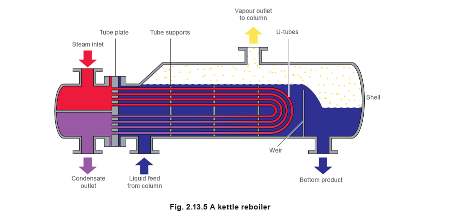
In forced circulation reboilers the secondary fluid is pumped through the exchanger, whilst in thermosyphon reboilers natural circulation is maintained by differences in density. In kettle reboilers there is no circulation of the secondary fluid, and the tubes are submerged in a pool of liquid.
Table 2.13.3 Typical heat transfer coefficients for some shell and tube heat exchangers
| Secondary Fluid | U (W/m2 °C) |
| Water | 1 500 - 4 000 |
| Organic solvents | 500 - 1 000 |
| Light oils | 300 - 900 |
| Heavy oils | 60 - 450 |
| Gases | 30 - 300 |
| Aqueous solutions (vaporising) | 1 000 - 1 500 |
| Light organics (vaporising) | 1 900 - 1 200 |
| Heavy organics (vaporising) | 600 - 900 |
Although it is desirable to achieve dropwise condensation in all these applications, it is often difficult to maintain and is unpredictable. To remain practical, design calculations are generally based on the assumption of filmwise condensation.
The heat transfer area for a shell and tube heat exchanger may be estimated using Equation 2.5.3. Although these units will also normally be specified in consultation with the manufacturers, some typical overall heat transfer coefficients where steam is used as the heating medium (and which include an allowance for fouling) are provided in Table 2.13.3, as a guide.
Corrugated tube heat exchangers
One evolution in the design of the traditional shell and tube heat exchanger, is the recent development of the corrugated tube heat exchanger. This is a single passage fixed plate heat exchanger with a welded shell, and rectilinear corrugated tubes that are suitable for low viscosity fluids. In a similar manner to the plate heat exchangers, the corrugated tubes promote turbulent operating conditions that maximise heat transfer and reduce fouling. Like the traditional shell and tube heat exchangers, these units are commonly installed horizontally. However, in the corrugated tube heat exchanger the steam should always be on the shell side.
Spiral heat exchangers
Spiral heat exchangers share many similar characteristics with shell and tube and plate heat exchangers and are used on many of the same applications. They consist of fabricated metal sheets that are cold worked and welded to form a pair of concentric spiral channels, which are closed by gasketed end-plates bolted to an outer case.
Turbulence in the channels is generally high, with identical flow characteristics being obtained for both fluids. They are also relatively easy to clean and can be used for very heavy fouling fluids and slurries. The use of only a single pass for both fluids, combined with the compactness of the unit, means that pressure drops across the connections are usually quite low.
