Steam Traps and Steam Trapping

Contents
Testing of Steam Traps
Traditional and contemporary methods
Indiscriminate maintenance of steam traps costs money. Steam traps will either be:
- In good working order.
- Leaking steam.
- Blocking flow.
A major problem has always been the accurate identification of faulty traps. Wrong diagnosis can allow faulty traps to remain troublesome, and perfectly sound traps to be replaced unnecessarily.
Accurate diagnosis is therefore important to any maintenance programme.
Historically, diagnostic methods have included listening devices, optical sight glasses, temperature monitoring, and ultrasonic techniques. All of these can give an indication of flow, but become inaccurate as system conditions change. Noise level will vary with disturbance from adjacent traps, and condensate load. Interpretation of signals is difficult even for experienced operators.
Sight glasses offer a partial solution, especially the combined sight/check valve that gives a visual indication of flow plus a non-return facility, however, glasses will require changing occasionally.
The inadequacies of listening devices have led to temperature monitoring, but it is perfectly feasible (and normal) for condensate and steam to coexist at the same temperature in the same system, making accurate diagnosis difficult on temperature alone.
A modern version of the listening rod is the ultrasonic trap tester which detects ultrasound generated by a leaking trap. In the hands of a trained and experienced operator, the ultrasonic tester can be used to good effect, but in the hands of a novice, it is easy to draw the wrong diagnosis i.e. that the trap has failed whereas, in fact, it has not.
The unreliability of the above methods has prompted the development of an integrated and fool proof steam trap testing device.
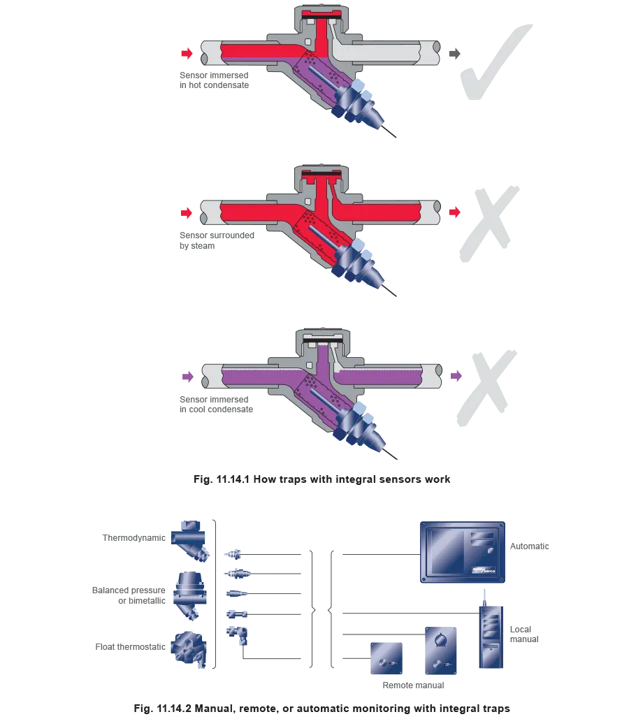
This consists of a sensor, fitted inside the steam trap, which is capable of detecting the physical state of the medium at that point by conductivity (Figure 11.14.1). It is not affected by flash steam disturbance. The result is finite and not subject to interpretation. Monitoring can be done locally, remotely, manually or automatically, and can detect immediate failure, thus minimising waste and maximising investment (Figure 11.14.2).
An integral thermocouple in the sensing chamber can detect and help to predict blockages, which is particularly useful, especially to those Hydrocarbon and Processing Industries which require process continuity.
For steam users preferring to use steam traps without integral sensors, or for larger applications requiring larger traps, sensors can be provided in separate sensor chambers (see Figures 11.14.3, 11.14.4 and 11.14.5).

Maintenance of steam traps
Routine maintenance
Routine maintenance depends on the type of trap and its application. The balanced pressure steam trap for example, has an element which is designed for easy replacement. Changing these on a regular basis, maybe once every three years or so, might seem wasteful in time and materials. However, this practice reduces the need for trap checking and should ensure a trouble free system with minimal losses through defective traps.
Routine maintenance which involves cleaning and re-using existing internals uses just as much labour but leaves an untrustworthy steam trap. It will have to be checked from time to time and will be prone to fatigue. Any routine maintenance should include the renewal of any suspect parts, if it is to be cost effective.
Replacement of internals
The renewal of internal parts of a steam trap makes good sense. The body will generally have as long a life as the plant to which it is fitted and it is only the internal parts which wear, depending on system conditions. There are obvious advantages in replacing these internals from time to time. It depends on the ease with which the new parts can be fitted and the reliability and availability of the refurbished trap. The elements of thermostatic traps can generally be changed by removing a screwed in seat. Replacement is simple and the remade trap will be reliable assuming the maintenance instructions are correctly carried out.
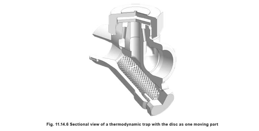
If the seat or disc faces of a thermodynamic trap become damaged, the disc can simply be replaced (Figure 11.14.6). Damage to seating faces can be rectified by lapping gently. Replacing the seats of some higher pressure thermodynamic traps is more complicated. Two separate gasketed joints may have to be made or a single gasket may have to cope with two or more steam/condensate passages. The weakest point is often the joint between trap body and seat, particularly if this has been allowed to blow steam.
Always check with the manufacturer regarding the correct technique for any maintenance work required on steam traps. A reputable manufacturer will always be able to supply appropriate literature, advice, and spare parts.
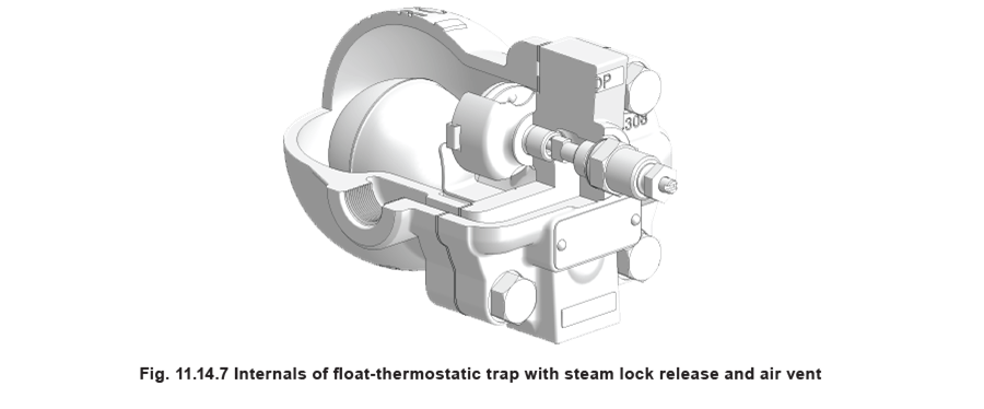
A lot will depend on site conditions. The small float trap, shown in Figure 11.14.7, is designed so that the cover with the internals attached can be taken to the workshop, leaving the main body attached to the pipe. This is often preferable to renewing the seats of inaccessible traps, which have been welded into the pipework under dirty site conditions.
Replacement of traps
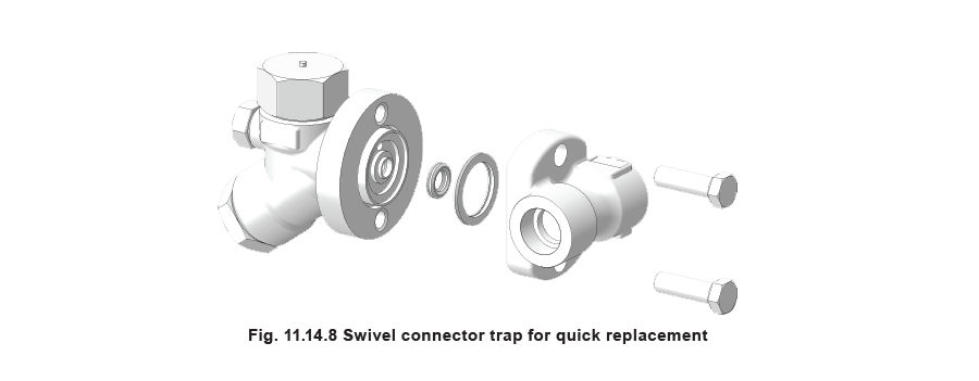
On occasions, it will be easier and cheaper to replace traps rather than repair them. In these cases it is essential that the traps themselves can be changed easily. Flanged connections provide one solution, although the flanged trap is more expensive than the equivalent screwed trap. Mating flanges are an additional expense.
A swivel connector allows rapid easy removal and replacement of the sealed trap. The trap shown in Figure 11.14.8 is specifically designed for easy replacement for such a system. It comprises a pipeline unit or connector which remains in the pipeline during the maintenance procedure. The trap can be replaced simply by attending to two bolts. This type of trap can be matched to the same connector providing flexibility of choice and rationalisation of spares. Connectors are also available with integral piston isolation valves ensuring downtime is kept to a minimum.