The Boiler House

Contents
Boiler Fittings and Mountings
An overview of the necessary fittings, accessories and controls for a boiler from nameplates and safety valves to gauge glasses and level controls.
Boiler name-plate
In the latter half of the 19th century explosions of steam boilers were commonplace. As a consequence of this, a company was formed in Manchester with the objective of reducing the number of explosions by subjecting steam boilers to independent examination. This company was, in fact, the beginning of today’s Safety Federation (SAFed), the body whose approval is required for boiler controls and fittings in the UK.
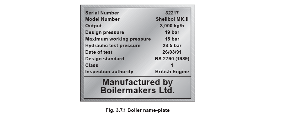
After a comparatively short period, only eight out of the 11 000 boilers examined exploded. This compared to 260 steam boiler explosions in boilers not examined by the scheme. This success led to the Boiler Explosions Act (1882) which included a requirement for a boiler name-plate. An example of a boiler name-plate is shown in Figure 3.7.1.
The serial number and model number uniquely identify the boiler and are used when ordering spares from the manufacturer and in the main boiler log book.
The output figure quoted for a boiler may be expressed in several ways, as discussed in previous Modules within this Block.
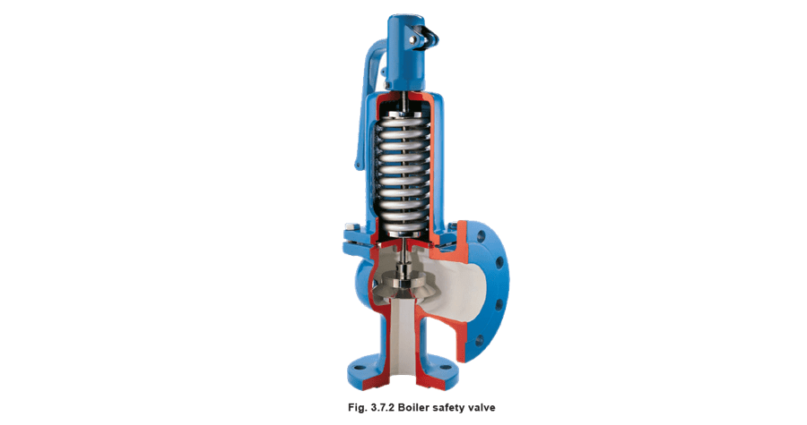
Safety valves
An important boiler fitting is the safety valve. Its function is to protect the boiler shell from over pressure and subsequent explosion. In the UK:
In Europe, matters relating to the suitability of safety valves for steam boilers are governed by the European standard EN 12953. In the US and some other parts of the world, such matters are covered by ASME standards.
Many different types of safety valves are fitted to steam boiler plant, but generally they must all meet the following criteria:
- The total discharge capacity of the safety valve(s) must be at least equal to the ‘from and at 100°C’ capacity of the boiler. If the ‘from and at’ evaporation is used to size the safety valve, the safety valve capacity will always be higher than the actual maximum evaporative boiler capacity.
- The full rated discharge capacity of the safety valve(s) must be achieved within 110% of the boiler design pressure.
- The minimum inlet bore of a safety valve connected to a boiler shall be 20 mm.
- The maximum set pressure of the safety valve shall be the design (or maximum permissible working pressure) of the boiler.
- There must be an adequate margin between the normal operating pressure of the boiler and the set pressure of the safety valve.
Safety valve regulations (UK)
A boiler shall be fitted with at least one safety valve sized for the rated output of the boiler - Refer to EN 12953 for details.
The discharge pipework from the safety valve must be unobstructed and drained at the base to prevent the accumulation of condensate. It is good practice to ensure that the discharge pipework is kept as short as possible with the minimum number of bends, so that the allowable backpressure indicated by the valve manufacturer is not exceeded.
It will be quite normal for the internal diameter of the discharge pipework to be more than the internal diameter of the safety valve outlet connection, but under no circumstances should it be less.
Boiler stop valves
A steam boiler must be fitted with a stop valve (also known as a crown valve) which isolates the steam boiler and its pressure from the process or plant. It is generally an angle pattern globe valve of the screw-down variety. Figure 3.7.3 shows a typical stop valve of this type.
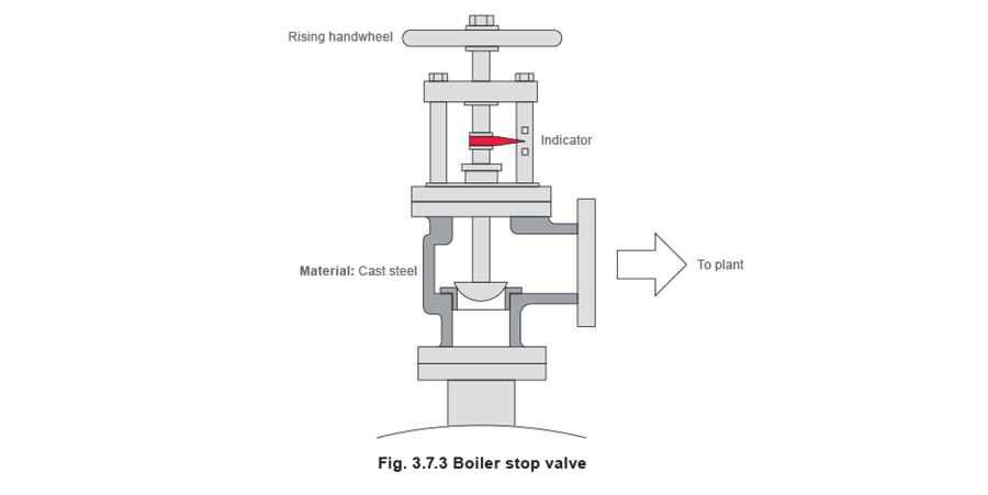
In the past, these valves have often been manufactured from cast iron, with steel and bronze being used for higher pressure applications. In the UK, BS 2790 (eventually to be replaced with EN 12953) states that cast iron valves are no longer permitted for this application on steam boilers. Nodular or spheroidal graphite (SG) iron should not be confused with grey cast iron as it has mechanical properties approaching those of steel. For this reason many boilermakers use SG iron valves as standard.
The stop valve is not designed as a throttling valve, and should be fully open or closed. It should always be opened slowly to prevent any sudden rise in downstream pressure and associated waterhammer, and to help restrict the fall in boiler pressure and any possible associated priming.
To comply with UK regulations, the valve should be of the ‘rising handwheel’ type. This allows the boiler operator to easily see the valve position, even from floor level. The valve shown is fitted with an indicator that makes this even easier for the operator.
On multi-boiler applications an additional isolating valve should be fitted, in series with the crown valve. At least one of these valves should be lockable in the closed position. The additional valve is generally a globe valve of the screw-down, non-return type which prevents one boiler pressurising another. Alternatively, it is possible to use a screw-down valve, with a disc check valve sandwiched between the flanges of the crown valve and itself.
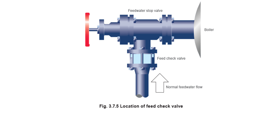
Feedwater check valves
The feedwater check valve (as shown in Figures 3.7.4 and 3.7.5) is installed in the boiler feedwater line between the feedpump and boiler. A boiler feed stop valve is fitted at the boiler shell.
The check valve includes a spring equivalent to the head of water in the elevated feedtank when there is no pressure in the boiler. This prevents the boiler being flooded by the static head from the boiler feedtank.

Under normal steaming conditions the check valve operates in a conventional manner to stop return flow from the boiler entering the feedline when the feedpump is not running. When the feedpump is running, its pressure overcomes the spring to feed the boiler as normal.
Because a good seal is required, and the temperatures involved are relatively low (usually less than 100°C) a check valve with a EPDM (Ethylene Propylene) soft seat is generally the best option.
Boiler water quality control
The maintenance of water quality is essential to the safe and efficient operation of a steam boiler. The measurement and control of the various parameters is a complex topic, which is also covered by a number of regulations. It is therefore covered in detail later in this Block. The objective of the next few Sections is simply to identify the fittings to be seen on a boiler.
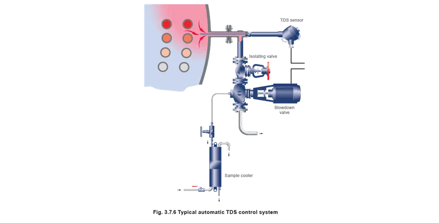
TDS control
This controls the amount of Total Dissolved Solids (TDS) in the boiler water, and is sometimes also referred to as ‘continuous blowdown’. The boiler connection is typically DN15 or DN20. The system may be manual or automatic. Whatever system is used, the TDS in a sample of boiler water is compared with a set point; if the TDS level is too high, a quantity of boiler water is released to be replaced by feedwater with a much lower TDS level. This has the effect of diluting the water in the boiler, and reducing the TDS level.
On a manually controlled TDS system, the boiler water would be sampled every shift.
A typical automatic TDS control system is shown in Figure 3.7.6
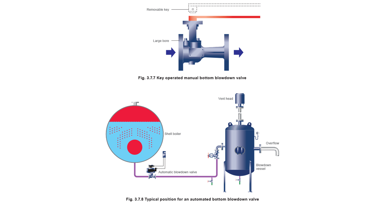
Bottom blowdown
This ejects the sludge or sediment from the bottom of the boiler. The control is a large (usually DN25 to DN50) key operated valve. This valve might normally be opened for a period of about 5 seconds, once per shift.
Figure 3.7.7 illustrates a key operated manual bottom blowdown valve whereas Figure 3.7.8 illustrates an automated bottom blowdown valve and its typical position in a blowdown system.

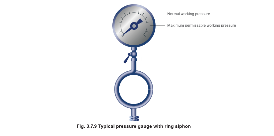
Pressure gauge
All boilers must be fitted with at least one pressure indicator.
The usual type is a simple pressure gauge constructed to EN 12953.
The dial should be at least 150 mm in diameter and of the Bourdon tube type, it should be marked to indicate the normal working pressure and the maximum permissible working pressure / design pressure.
Pressure gauges are connected to the steam space of the boiler and usually have a ring type siphon tube which fills with condensed steam and protects the dial mechanism from high temperatures.
Pressure gauges may be fitted to other pressure containers such as blowdown vessels, and will usually have smaller dials as shown in Figure 3.7.9.
Gauge glasses and fittings
All steam boilers are fitted with at least one water level indicator, but those with a rating of 100 kW or more should be fitted with two indicators. The indicators are usually referred to as gauge glasses complying with EN 12953.
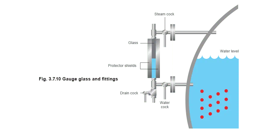
A gauge glass shows the current level of water in the boiler, regardless of the boiler’s operating conditions. Gauge glasses should be installed so that their lowest reading will show the water level at 50 mm above the point where overheating will occur. They should also be fitted with a protector around them, but this should not hinder visibility of the water level. Figure 3.7.10 shows a typical gauge glass.
Gauge glasses are prone to damage from a number of sources, such as corrosion from the chemicals in boiler water, and erosion during blowdown, particularly at the steam end. Any sign of corrosion or erosion indicates that a new glass is required.
When testing the gauge glass steam connection, the water cock should be closed. When testing the gauge glass water connections, the steam cock pipe should be closed.
To test a gauge glass, the following procedure should be followed:
1. Close the water cock and open the drain cock for approximately 5 seconds.
2. Close the drain cock and open the water cock
Water should return to its normal working level relatively quickly. If this does not happen, then a blockage in the water cock could be the reason, and remedial action should be taken as soon as possible.
3. Close the steam cock and open the drain cock for approximately 5 seconds.
4. Close the drain cock and open the steam cock.
If the water does not return to its normal working level relatively quickly, a blockage may exist in the steam cock. Remedial action should be taken as soon as possible.
The authorised attendant should systematically test the water gauges at least once each day and should be provided with suitable protection for the face and hands, as a safeguard against scalding in the event of glass breakage.
Note: that all handles for the gauge glass cocks should point downwards when in the running condition.
Gauge glass guards
The gauge glass guard should be kept clean. When the guard is being cleaned in place, or removed for cleaning, the gauge should be temporarily shut-off.
Make sure there is a satisfactory water level before shutting off the gauge and take care not to touch or knock the gauge glass. After cleaning, and when the guard has been replaced, the gauge should be tested and the cocks set in the correct position.
Maintenance
The gauge glass should be thoroughly overhauled at each annual survey. Lack of maintenance can result in hardening of packing and seizure of cocks. If a cock handle becomes bent or distorted special care is necessary to ensure that the cock is set full open. A damaged fitting should be renewed or repaired immediately. Gauge glasses often become discoloured due to water conditions; they also become thin and worn due to erosion. Glasses, therefore, should be renewed at regular intervals.
A stock of spare glasses and cone packing should always be available in the boiler house. Remember:
- If steam passes are choked a false high water level may be given in the gauge glass. After the gauge has been tested a false high water level may still be indicated.
- If the water passages are choked an artificially high water level may be observed due to steam condensing in the glass. After testing, the glass will tend to remain empty unless the water level in the boiler is higher than the top connection, in which case water might flow into the glass from this connection.
- Gauge glass levels must be treated with the utmost respect, as they are the only visual indicator of water level conditions inside the boiler. Any water level perceived as abnormal must be investigated as soon as it is observed, with immediate action taken to shut down the boiler burner if necessary.
Water level controls
The maintenance of the correct water level in a steam boiler is essential to its safe and efficient operation. The methods of sensing the water level, and the subsequent control of water level is a complex topic that is covered by a number of regulations. The following few Sections will provide a brief overview, and the topic will be discussed in much greater detail later.
External level control chambers
Level control chambers are fitted externally to boilers for the installation of level controls or alarms, as shown in Figure 3.7.11.
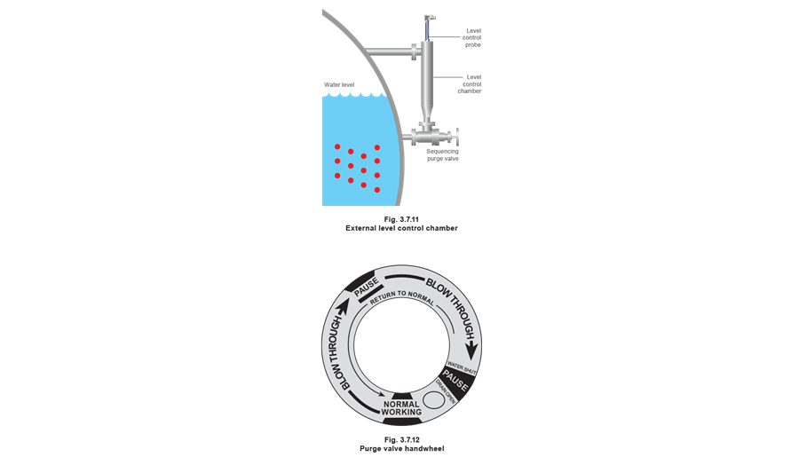
The function of the level controls or alarms is checked daily using the sequencing purge valves. With the handwheel turned fully anticlockwise the valve is in the ‘normal working’ position and a back seating shuts off the drain connection. The handwheel dial may look similar to that shown in Figure 3.7.12. Some handwheels have no dial, but rely on a mechanism for correct operation.

The following is a typical procedure that may be used to test the controls when the boiler is under pressure, and the burner is firing:
- Slowly turn the handwheel clockwise until the indicating pointer is at the first ‘pause’ position. The float chamber connection is baffled, the drain connection is opened, and the water connection is blown through.
- Pause for 5 to 8 seconds.
- Slowly move the handwheel further clockwise to full travel. The water connection is shut-off, the drain valve remains open, and the float chamber and steam connections are blown through. The boiler controls should operate as for lowered water level in boiler i.e. pump running and / or audible alarm sounding and burner cut-out. Alternatively if the level control chamber is fitted with a second or extra low water alarm, the boiler should lock-out.
- Pause for 5 to 8 seconds.
- Slowly turn the handwheel fully anticlockwise to shut-off against the back seating in the ‘normal working’ position.
- Sequencing purge valves are provided by a number of different manufacturers. Each may differ in operating procedure. It is essential that the manufacturer’s instructions be followed regarding this operation.
Internally mounted level controls
Level control systems with sensors (or probes) which fit inside the boiler shell (or steam drum) are also available. These provide a higher degree of safety than those fitted externally. The level alarm systems may also provide a self-checking function on system integrity.
Because they are mounted internally, they are not subject to the procedures required to blow down external chambers. System operation is tested by an evaporation test to ‘1st low’ position, followed by blowing down to ‘2nd low’ position.
Protection tubes are fitted to discourage the movement of water around the sensor.

Air vents and vacuum breakers
When a boiler is started from cold, the steam space is full of air. This air has no heat value, and will adversely affect steam plant performance due to its effect of blanketing heat exchange surfaces. The air can also give rise to corrosion in the condensate system, if not removed adequately.
The air may be purged from the steam space using a simple cock; normally this would be left open until a pressure of about 0.5 bar is showing on the pressure gauge. An alternative to the cock is a balanced pressure air vent which not only relieves the boiler operator of the task of manually purging air (and hence ensures that it is actually done), it is also much more accurate and will vent gases which may accumulate in the boiler. Typical air vents are shown in Figure 3.7.14.
When a boiler is taken off-line, the steam in the steam space condenses and leaves a vacuum. This vacuum causes pressure to be exerted on the boiler from the outside, and can result in boiler inspection doors leaking, damage to the boiler flat plates and the danger of overfilling a shutdown boiler. To avoid this, a vacuum breaker (see Figure 3.7.14) is required on the boiler shell.