The Boiler House

Contents
Installation of Level Controls
The pros and cons of direct versus externally mounted level controls.
It has already been acknowledged that the water level in a steam boiler varies considerably as a result of:
- The load.
- The rate of load change.
- Water circulation within the boiler.
These circumstances combine to make it very difficult to monitor and control the boiler water level to any accuracy. What is required is a calm area of water which is representative of the actual boiler water level.
With float and probe type level controls, this is achieved in two ways:
- External chambers.
- Internal protection tubes.
External chambers
These are externally mounted chambers which have pipe connections to the boiler. They are usually, but not always, fitted with float controls. Some typical arrangements are shown in Figure 3.19.1.
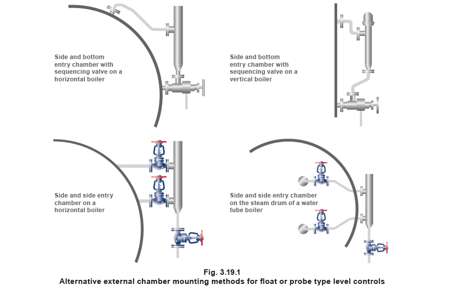
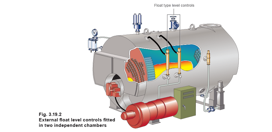
Two external chambers are required
- One chamber houses the level control plus the first low level alarm.
- The other houses the second low level alarm plus the high level alarm (if fitted).
This ensures that the two low alarms are in independent chambers.
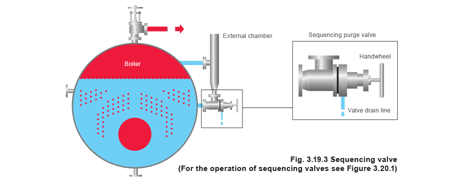
The external chambers would be fitted with ‘sequencing purge valves’ and (optionally) with steam isolating valves.
Note: If isolating valves are fitted, UK regulations demand that they are locked open.
Traditionally float controls have been installed into external chambers, although probes workequally well, and have the advantage of no moving parts to wear out.
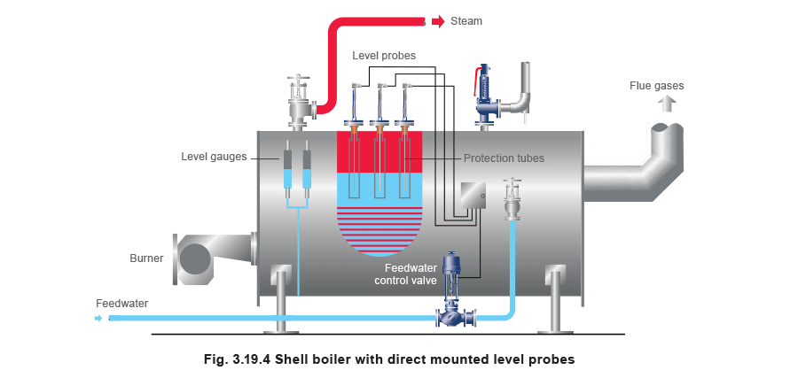
Internal protection tubes (direct mounted level controls)
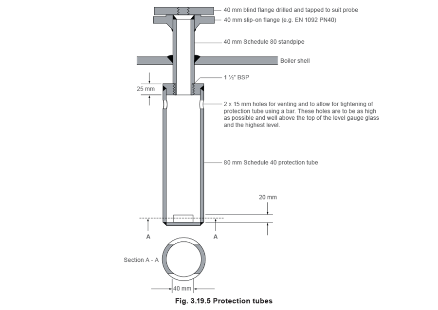
These are sometimes referred to as direct mounted level controls, and they require protection tubes to be installed inside the boiler shell as shown in Figure 3.19.4.
The first and second low level devices must be mounted in separate protection tubes, so that they are completely independent of each other.
The protection tubes themselves are not standard items, and will be uniquely manufactured for each individual boiler. However, because the design of the protection tubes can have such a major effect on the successful operation of the level controls, the following provide some guidance for their design and installation:
Diameter
An 80 mm nominal bore protection tube will ensure steady conditions and provide sufficient clearance for probe centering.
Where two probes (for example, level control/high alarm probe plus self-monitoring low alarm probe) are to be installed in a single protection tube, 100 mm nominal bore is usually required.
Length
The protection tube should go as far down between the boiler tubes as physically possible.
Location
Where there is a choice of probe installation positions, the general recommendations are as follows:
- As far away as possible from the steam off-take and safety valve connection (minimum 1 m), but not too near the boiler end plates.
- As close to the level gauge as possible. Connections across the boiler shell, near the front are often convenient.
- Installation in protection tubes with top and bottom holes for steam and water entry, with a blanked bottom to prevent steam bubbles entering and without a full length slot along the protection tube.
There are a number of significant advantages to using direct mounted controls in internal protection tubes:
- It is often a cheaper alternative with a new boiler as the cost of two or three protection tubes is usually less than two external control chambers and the associated sequencing purge valves.
- Full advantage can be taken of the advances in electronics provided by modern technology.
Float controls
Although the trend is towards using probe-type direct mounted controls, it is still common to see direct mounted float controls, where the float is situated inside the boiler shell using a flange and protection tube assembly.
Standard models
Direct mounted float controls employ the same principles of operation and piece parts as their chamber mounted equivalents, except that the chamber is exchanged for a large round flange and protection tube assembly for mounting the control directly onto the boiler shell connection. The protection tube may be fixed or removable, and will ensure that the float rod is not damaged and the correct vertical movement is achieved.
Direct mounted float controls incorporating test facilities
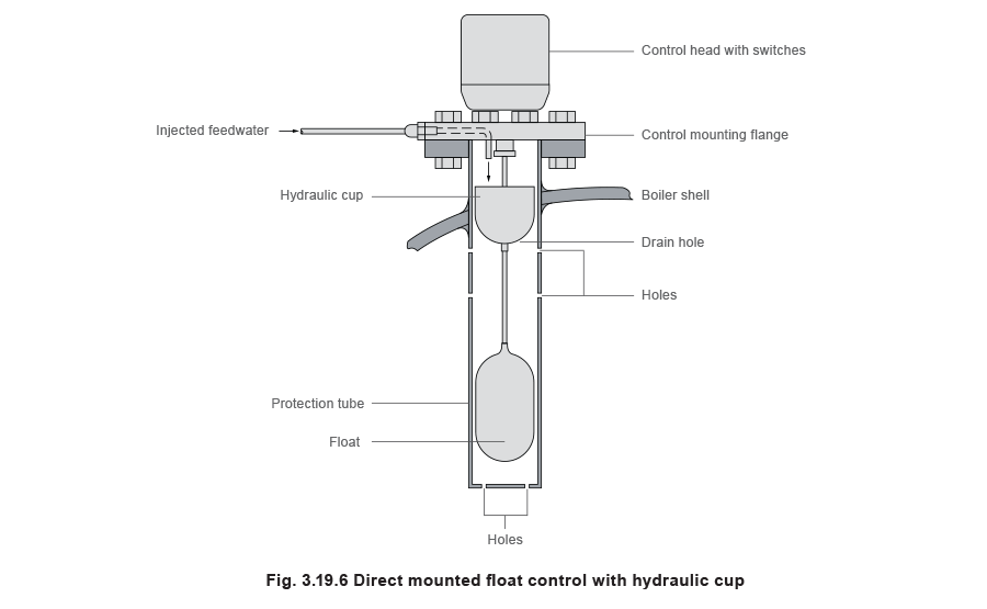
To comply with the UK HSE Guidance Note for unmanned boiler houses, direct mounted float controls may incorporate a facility for testing the operation of the mechanism without lowering the level of water in the boiler. Testing can be manual, or initiated/controlled by a timer. The test is achieved by lowering the float to the low water alarm level.
Hydraulic cup test facility
The test is achieved by lowering the float to the low water alarm level, by the following means:
The float rod includes a cup above the float, which is fed for approximately 24 seconds with water from the boiler feedpump, via small bore pipework and valves, through the control mounting flange (see Figure 3.19.6).
The additional weight overcomes the buoyancy of the float, causing it to sink. This stops the burner from firing and operates the alarm system. After closing the test valve in the supply from the feedpump to the control, a small hole in the bottom of the cup drains off the water, permitting the float to rise to the normal operating position. Control of the water supply to the cup can also be achieved by means of a solenoid valve, which can be initiated by a timer or a manually operated push button.
Electromagnetic test facility
The switch head includes a solenoid coil below the single switch sub-assembly. This surrounds an armature, which is located inside the stainless steel centre tube and fixed to the float rod.
To initiate the test cycle, the coil can be energised by a timer or a manually operated push button, and the float will be thrust downwards, to stop the burner firing and thus operate the alarm system. When the coil is de-energised the float rises to its normal level.
Probe controls
Single channel (non self-monitoring high integrity probes) may be installed in protection tubes, and, because they have no moving parts, they will often last longer than an equivalent float control system.
The use of internal protection tubes in conjunction with high integrity, self-monitoring probes and controllers, brings significant advantages in terms of testing requirements and the level of supervision demanded by authorities such as the UK Health and Safety Executive. This is discussed further in the next Module.