The Boiler House

Contents
Steam Headers and Off-takes
This tutorial looks at steam header arrangements and other design considerations necessary for efficient warm-up, good steam quality and proper steam distribution from the boiler house.
Steam Headers and Off-takes
Shell boilers are made for capacities up to around 27000 kg/h of steam. When loads in excess of this are required, two or more boilers are connected in parallel, with an installation of four or more boilers not being uncommon. The design of the interconnecting steam header is highly important.
Figure 3.8.1 shows a common method of connecting four boilers: a method that is frequently a source of problems.
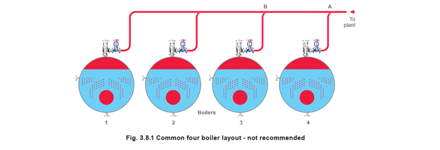
Referring to Figure 3.8.1, with all boilers operating at the same pressure, the pressure at point A has to be less than that at point B for steam to flow from point B to the plant. Consequently, there must be a greater pressure drop between boiler number 4 and point A than boiler number 3 and point B, whilst the difference in these two pressure drops takes place between A and B.
Flow depends on pressure drop, it follows then, that boiler number 4 will discharge more steam into the common header than boiler number 3. Likewise, boiler number 3 will discharge more than number 2, and so on. The net effect is that if boiler number 1 is fully loaded, the other boilers are progressively overloaded, the effect worsening nearer to the final off-take.
It can be shown that, typically, if boiler number 1 is fully loaded, number 2 will be around 1% overloaded, number 3 around 6%, and number 4 around 15% overloaded. Whilst shell boilers are able to cope with occasional overload conditions of 5%, an overload of 15% is undesirable.
The increased steam outlet velocity from the boiler creates an extremely volatile water surface, and the level control system might fail to control.
At high loads, in this example, boiler number 4 would lock-out, throwing an already unstable system onto the three remaining boilers, which would soon also lock-out.
The main observation is that this design of distribution header does not allow the boilers to share the load equally.
The aim should be that the pressure drops between each boiler outlet and the header off-take to the plant should be within 0.1 bar. This will minimise carryover and help to prevent overload and lockout of boilers.
The layout shown in Figure 3.8.2 shows an improved design of a new header.
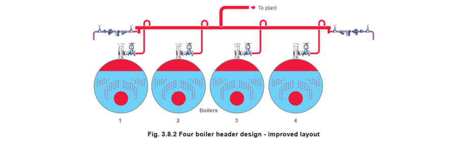
The header is arranged to discharge from the centre, rather than at one end. In this way, no boiler will be overloaded by the header by more than 1%, providing the header pipework is properly sized.
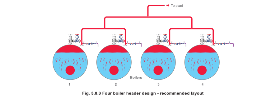
A better arrangement is shown in Figure 3.8.3 for an installation of four or more boilers, rather like a family tree, where the load on each boiler is spread equally. This arrangement is recommended for heavily loaded boilers, with sequencing control where one or more is regularly off-line.
It is emphasised that correct header design will save much trouble and expense later.
Correct boiler header design on multi-boiler applications will always result in a well-balanced operation.
Steam off-takes
Having considered the general arrangement of the steam header, the following conditions need to be ensured:
- That dry steam is exported to the plant.
- That the warm-up operation is properly controlled.
- That steam is properly distributed to the plant.
- That one boiler cannot accidentally pressurise another.
Water carryover
When a well-designed boiler generates steam under steady load conditions, the dryness fraction of the steam will be high, approximately 96 to 99%. Changes in load that occur faster than the boiler can respond will adversely affect the dryness fraction. Poor control of boiler water TDS, or contamination of boiler feedwater, will result in wet steam being discharged from the boiler.
A number of problems are associated with this:
- Water droplets in steam pipes will tend to erode the inside of the pipe, and any other fittings,and valves, especially if velocities are high.
- Water in a steam system gives the potential for dangerous waterhammer.
- Water in steam does not contain the enthalpy of evaporation that the plant has been designed to use, so transporting it to the plant is inefficient.
- Water carried over with steam from a boiler will inevitably contain dissolved and suspended solids, which can contaminate controls, heat transfer surfaces, steam traps and the product.
For these reasons, a separator close to the boiler is recommended. Separators work by forcing the steam to rapidly change direction. This results in the much denser water particles being separated from the steam due to their inertia, and then encouraged to gravitate to the bottom of the separator body, where they collect and drain away via a steam trap.
Warm-up
It is essential that when a boiler is brought on line, it is done in a slow, safe and controlled manner to avoid:
- Waterhammer - Where large quantities of condensate lie inside the pipe and are then pushed along the pipe at steam velocities. This can result in damage when the water impacts with an obstruction in the pipe, for example a control valve.
- Thermal shock - Where the pipework is being heated so rapidly that the expansion is uncontrolled, setting up stresses in the pipework and causing large movement on the pipe supports.
- Priming - Where a sudden reduction of steam pressure caused by a large, suddenly applied load may result in boiler water being pulled into the pipework. Not only is this bad for plant operation, the boiler can often go to ‘lock-out’ and it will take some time to return the boiler to operating status. The discharged water can also give rise to waterhammer in the pipework.
The warm-up period for every plant will be different and will depend on many factors. A small low-pressure boiler in a compact plant such as a laundry, for example, could be brought up to operating pressure in less than 15 minutes. A large industrial complex may take many hours. The starting point, when safely bringing a small boiler on line, is the main stop valve, which should be opened slowly.
On larger plants, however, the rate of warm-up is difficult to control using the main stop valve. This is because the main stop valve is designed to provide good isolation; it has a flat seat that means that all the force exerted by turning the handwheel acts directly onto the seat, thus ensuring a good seal when under pressure. It also means that the valve is not characterised and will pass approximately 80% of its capacity in the first 10% of its movement.
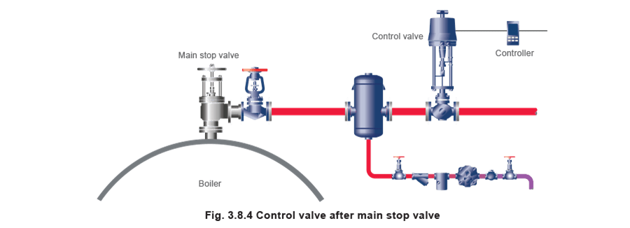
For this reason it is good practice to install a control valve after the main stop valve. A control valve has a profiled plug, which means that the relationship between an increase in flow and the movement of the plug is much less severe. Consequently the flowrate, and hence warm-up rate, is better controlled.
An example of a control valve fitted after the boiler main stop valve is shown in Figure 3.8.4.
A typical warm-up arrangement may be that the control valve is closed until the boiler is required.
At this point a pulse timer slowly opens the control valve over a predetermined time period. This arrangement also has the advantage that it does not require manpower (unless the boiler is heated up from cold) over the boiler warm-up period, which may be during twilight hours.
The subject of bringing boilers on-line is covered by the HSE guidelines in the UK.
On large distribution systems, a line size control valve is still often too coarse to provide the required slow warm-up. In these circumstances a small control valve in a loop around an isolation valve could be used. This also has the advantage that where parallel slide valves are used for isolation, the pressure can be equalised either side of the valve prior to opening. This will make them easier to open, and reduces wear.
Preventing one boiler pressurising another
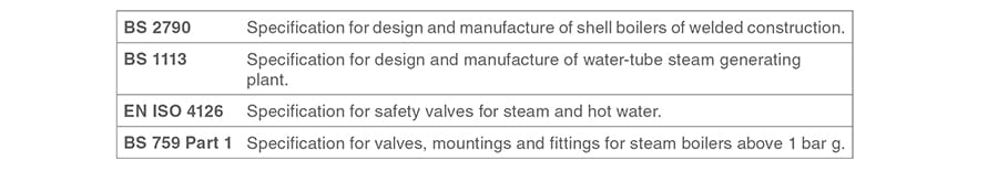
From BS 2790, Section 8.8.3.
Where two or more boilers are connected to a common header, in addition to the boiler main stop valve, a second valve shall be incorporated in the steam connection, and this valve shall be capable of being locked in the closed position. This allows better protection for a decommissionedboiler when isolated from the distribution header.
Unless a separate non-return valve is fitted in the steam connection, one of the two stop valves must incorporate a non-return facility.
The objective of this section of the British Standard is to provide safe working conditions when the boiler is shut down for repair or inspection.
Simple flap-type non-return valves are not suitable for this purpose, because small changes in boiler pressures can cause them to oscillate, placing excess load on to one boiler or the other alternately. This can, under severe conditions, cause cyclical overloading of the boilers.
Many cases of instability with two-boiler installations are caused in this way. Main stop valves with integral non-return valves tend to suffer less from this phenomenon. Alternatively, spring loaded disc check valves can provide a dampening effect which tends to reduce the problems caused by oscillation (Figure 3.8.5).
BS 2790 states that a non-return valve must be fitted in this line together with the main stop valve, alternatively, the main stop valve must incorporate an integral non-return valve.

Boiler related standards (UK)
Statutory instrument 1989 No. 2169 (The pressure systems and transportable gas containers regulations 1989) with the associated guide and approved code of practice.
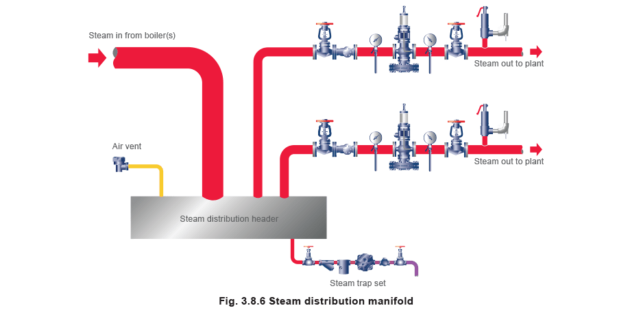
Ensuring proper steam distribution
The starting point for the distribution system is the boiler house, where it is often convenient for the boiler steam lines to converge at a steam manifold usually referred to as the main distribution header. The size of the header will depend upon the number and size of boilers and the design of the distribution system. In a large plant, the most practical approach is to distribute steam via a high pressure main around the site.
High pressure distribution is generally preferred as it reduces pipe sizes relative to capacities and velocities. Heat losses may also be reduced due to lower overall pipe diameters. This allows steam supplies to be taken from the main, either direct to high pressure users, or to pressure reducing stations providing steam to local users at reduced pressure. A steam header at the boiler house provides a useful centralised starting point.
It provides an extra separating function if the boiler separator is overwhelmed, and a means of allowing the attached boilers to share the distribution system load.
Operating pressure
The header should be designed for the boiler operating pressure and to conform to the Pressure Systems Regulations. It is important to remember that flange standards are based on temperature and pressure and that the allowable pressure reduces as the operating temperature increases.
For example, a PN16 rating is 16 bar at 120°C, but is only suitable for up to 13.8 bar saturated steam (198°C).
Diameter
The header diameter should be calculated with a maximum steam velocity of 15 m/s under full-load conditions. Low velocity is important as it helps any entrained moisture to fall out.
Off-takesout.
These should always be from the top of the distribution header.
Gravity and the low velocity will ensure that any condensate falls to and drains from the bottom of the header. This ensures that only dry steam is exported.
Steam trapping
It is important that condensate is removed from the header as soon as it forms. For this reason a mechanical trap, for instance a float trap, is the best choice. If the header is the first trapping point after the boiler off-takes, the condensate can contain carryover particles and it may be useful to drain this steam trap into the boiler blowdown vessel, rather than the boiler feedtank.
Related reading:
1. The Steam and Condensate Loop, Block 11, ‘Steam Trapping’
2. The Steam and Condensate Loop, Block 10, ‘Steam Distribution’