Steam Traps and Steam Trapping

Contents
Considerations for Selecting Steam Traps
Application type, system design and maintenance needs will influence the performance and selection of steam traps. Factors such as waterhammer, dirt, steam locking, group trapping, vacuum conditions and temperature control of processes are discussed in this tutorial.
Considerations
By definition, a steam trap must trap or hold back steam whilst at the same time not restricting the passage of condensate, air, and other incondensable gases. The basic requirements of good steam trapping have already been outlined but it is worth repeating that the performance of the plant is paramount. The trap selection follows on the basis that the requirements of pressure, condensate load and air venting have been met, in the provisional selection. However, system design and maintenance needs will also influence performance and selection. Please refer to the following sub-sections in this Module for further advice on this matter.
Waterhammer
Waterhammer is a symptom of a problem in the steam system. This could be due to poor design of the steam and condensate pipework, the use of the wrong type of trap or traps or a leaking steam trap, or a combination of these factors. It is often futile to install the correct trap for an application if the system layout will not allow the trap to operate correctly. It is equally pointless to install the correct layout and not pay proper attention to steam trapping. The Modules 11.6 to 11.11 inclusive 'Selecting steam traps' will deal with the correct matching of steam traps to applications and layouts. The proper layout of steam pipework is also dealt with in Block 10 - 'Steam Distribution'. Symptoms of waterhammer are often attributed to malfunction of the steam trap. A more likely explanation is that a faulty steam trap has been damaged by waterhammer. Waterhammer can be caused in a number of ways, including:-
- Failure to remove condensate from the path of high velocity steam in the pipework.
- From an application which is temperature controlled and where condensate has to lift to a return line, or return to a pressurised system.
- The inability of condensate to properly enter or travel along an undersized return line, due to either (a) flooding, or (b) overpressurisation with the throttling effects of flash steam.
Modern design and manufacturing techniques have produced steam traps which are more robust than those of their predecessors. This allows the steam trap to last longer under normal conditions, and will also be better able to withstand the effects of poorly designed systems. Basically, however well a steam trap is made, if it is installed in a poorly designed system it will be less effective and have a shorter working life.
If a steam trap persistently fails on an established system due to waterhammer, it is probably the fault of the system layout, rather than the trap. The solution is to investigate and eradicate the true cause of the problem by correcting the system inadequacies.
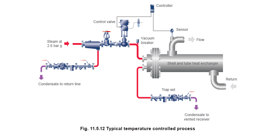
Two important applications are the drainage of steam mains, and of temperature controlled heat exchangers.
As a general rule, steam mains should be drained at regular intervals of 30 to 50 metres with adequately sized drain pockets. The bottom of any riser must also be drained.
Temperature controlled heat exchangers can only work effectively if condensate is allowed to drain freely from them. If there is a lift after the trap, there will always be a tendency for waterhammer, whichever trap is fitted. In this situation, the trap should either be complemented with a pump, or changed for a punp-trap . This subject will be dealt with in further detail in Block 13 - 'Condensate Removal'
It is important that the pipework is designed and installed correctly. This will help to maintain thermal performance of the system throughout its service life.
Dirt
Dirt is another major factor which must be considered when selecting traps. Although steam condenses to distilled water, it can sometimes contain trace products of boiler feed treatment compound and natural minerals found in water. Pipe dirt created during installation and the products of corrosion also need to be considered.
An intermittent blast action trap is the least likely to be affected by dirt. In thermostatic traps this means that the balanced pressure thermostatic trap is preferable, although the larger flat valve associated with some diaphragm traps can cause difficulties.
The dribbling action of bimetallic traps, coupled with the arrangement of the valve stem passing through the seat, means that these are most prone to malfunction (due to added friction) or even to blockage. It is sometimes claimed that the sensor element can be readily cleaned and is not subject to fouling. However, fouling of the element is rarely a problem: the relevant parts are the 'dynamic clack' valve mechanism, which tends to be self-cleaning due to its positive opening action.
Float-thermostatic steam traps are quite resistant to dirt. As an extreme example, when draining concrete curing autoclaves, the residual sand which precipitates into the condensate can be carried through large float-thermostatic steam traps quite successfully, due to the low velocity flow through a relatively large orifice.
The inverted bucket trap has an air vent hole in the bucket. If this blocks, it can cause the trap to air-bind and be slow to react. If this happens, the scale or dirt blocking the air vent must be dislodged, which requires the trap to be removed from service.
The impulse trap is intolerant of dirty conditions. The fine clearance between plug and tapered sleeve is susceptible to high velocity flow and the plug will frequently stick in an intermediate position. The trap seizes in a fixed position and will either pass steam or condensate depending on the rate of condensation.
The fixed orifice device is least suited to dirty conditions. The hole is inherently small and frequently blocks. Enlarging the hole (as is sometimes done in desperation) destroys the concept of sizing on a fixed orifice. It is wasteful and in some cases merely delays the time until blockage re-occurs. A strainer is often supplied and fitted but this has to be extremely fine to be effective.
This simply transfers the blockage from the orifice trap to the strainer, which, in turn, requires regular downtime for cleaning.
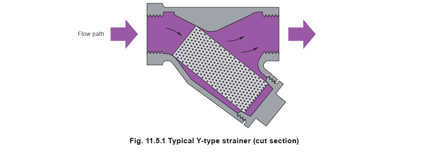
Strainers
These devices (Figure 11.5.1) are frequently forgotten about in steam systems, often, it seems, in an effort to reduce installation costs. Pipe scale and dirt can affect control valves and steam traps, and reduce heat transfer rates. It is extremely easy and inexpensive to fit a strainer in a pipe, and the low cost of doing so will pay dividends throughout the life of the installation. Scale and dirt are arrested, and maintenance is usually reduced as a result.
Selection is simple. The strainer material is selected to match the type of installation and the system pressure up to which it is expected to operate. Different filter screen sizes may be considered for differing degrees of protection. The finer the filter, the more often it may need cleaning. One thing is certain, strainers are far easier and cheaper to buy and maintain than control valves or steam traps.
Further information on strainers is given in Block 12 - 'Pipeline Ancillaries
Steam locking
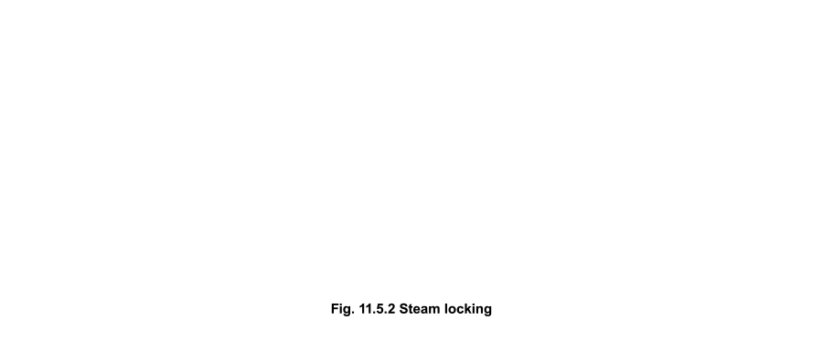
The possibility of steam locking can sometimes be a deciding factor in the selection of steam traps. It can occur whenever a steam trap is fitted remotely from the plant being drained. It can become acute when condensate is removed through a syphon or dip pipe. Figure 11.5.2 illustrates the problem of steam locking in a rotating drying cylinder by using a syphon pipe.
In Figure 11.5.2 (i) the steam pressure is sufficient to lift condensate up the syphon pipe, through the steam trap and away. Figure 11.5.2 (ii) shows what happens when the level of the condensate at the bottom of the cylinder falls below the end of the syphon pipe. Steam enters the syphon pipe and causes the steam trap (in this case a float type) to close.
The trap is temporarily 'steam locked'. Heat loss from the cylinder will result in the formation of more condensate which, as a result, is unable to reach the trap. Figure 11.5.2 (iii) shows the cylinder becoming increasingly waterlogged which will result in a reduced drying rate from the cylinder and an increase in the power required to turn the cylinder. In extreme cases the cylinder may fill to the centre line and damage may then result from mechanical overload
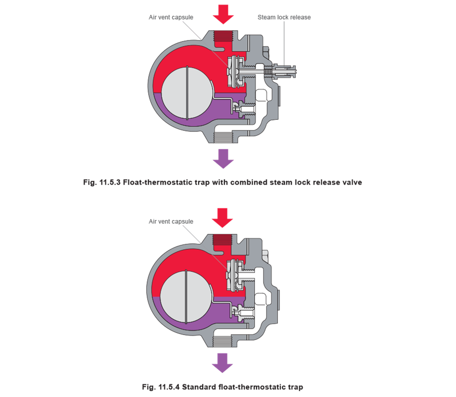
To relieve this problem a trap is needed with a 'steam lock release' valve. This is an internal needle valve which allows the steam locked in the syphon pipe to be bled away past the main valve. The float trap is the only type of trap with this facility and is the correct choice on rotating machinery such as drying cylinders. Because the needle valve is just open enough to avoid steam wastage it has a limited capacity to vent air. Traps of this type are often provided with combined air vents and steam lock release (Figure 11.5.3). The manually operated steam lock release mechanism works independently of the automatic air vent action. A standard float-thermostatic steam trap is shown in Figure 11.5.4
Other types of traps will open and eventually cope with a steam lock, however, the drainage and plant performance will be erratic. This is clearly unacceptable to users of process plant where batch times, quality and efficiency are of high importance.
Group trapping
Group trapping describes the use of one trap serving more than one application. Figure 11.5.5 shows two batch processes (jacketed pans) operating at two different steam pressures with the drain line from each connected to one steam trap. The higher pressure in plant B will allow condensate from this vessel to drain but will stop condensate being discharged from plant A as check valve C will be held closed. Plant A will waterlog and will suffer a severe drop in performance.
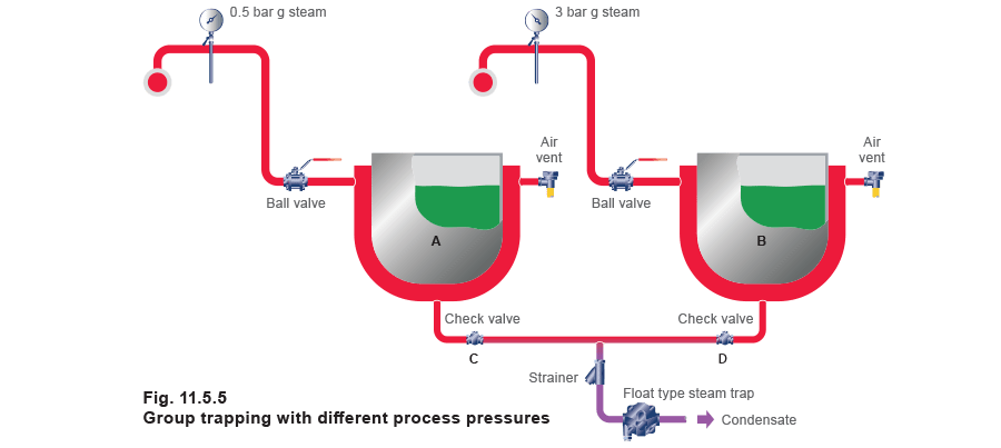
For this reason, group trapping of equipment operating at different pressures is not good practice. But what if equipment operates at the same pressure? Consider the following installation shown in Figure 11.5.6.
In Figure 11.5.6, the content of pan A is almost up to temperature and is condensing relatively little steam. Pans B, C and D have just been filled with cold product and, as the steam is turned on, their condensation rates are much higher than pan A. Consequently, the steam velocity along these supply pipes is much higher, resulting in a higher pressure drop along each of the branch lines. Lower steam pressures will exist at the pan inlets of B, C and D and in their steam jackets, (due to B, C and D having a higher condensing rate than pan A) reducing their heating ability and increasing their production times.
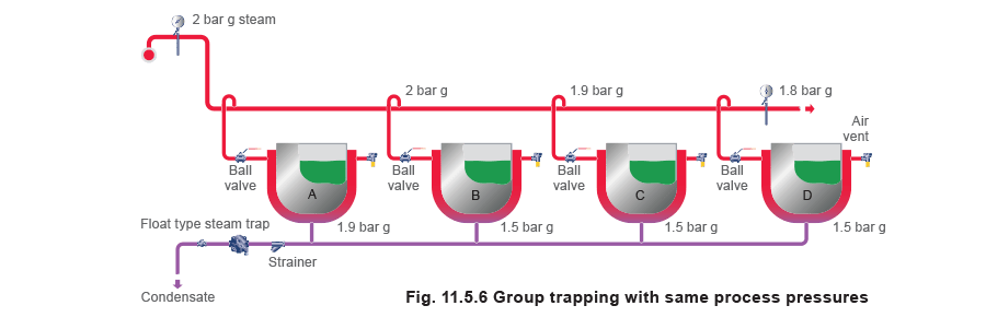
Because of this, the pressures at the drain outlets of pans B, C and D are also lower than that at pan A. Steam will flow from pan A via the condensate drain line to the other pans to equalise the pressures, and the condensate from the other pans will have to flow against this steam flow. When the drainage points of different vessels at different pressures are connected to one trap, the vessel with the highest pressure (in this instance pan A) will impede the flow of condensate from the others. Those vessels with the greatest need to discharge condensate (at this instance pans B, C and D) will tend to waterlog. Hence, the condensate arrangement shown in Figure 11.5.6 is unlikely to be satisfactory. The situation can be aggravated when group-trapped processes have separate temperature control.
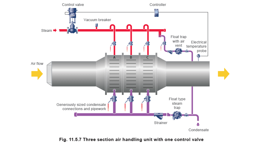
One possible application suitable for group trapping is an air handling unit with multiple heater sections in series (Figure 11.5.7).
This 'flow' type application differs from the batch (or non-flow) process in Figure 11.5.6. The heater sections will always share any load change as they are served by the same control valve. It is important that the condensate drain connections and common pipework are generously sized to allow adequate condensate flow in one direction against steam flow in the other. It will only work where all sections are fed by one control valve and the same secondary fluid is being heated by all sections.
The original reason for group trapping was that there used to be only one kind of steam trap. It was the forerunner of the present day bucket trap, and was very large and expensive. Steam traps today are considerably smaller and cost effective, allowing individual heat exchangers to be properly drained. It is always better for steam using equipment to be trapped on an individual basis rather than on a group basis.
In many instances it may be necessary to use a pump-trap on temperature controlled equipment, to remove condensate properly.
Diffusers
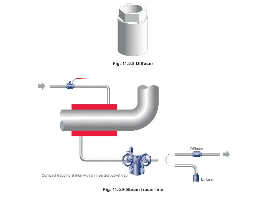
With steam traps draining to atmosphere from open ended pipes, it is possible to see the discharge of hot condensate. A certain amount of flash steam will also be present relative to the condensate pressure before the trap. This can present a hazard to passers by, but the risks can be minimised by reducing the severity of the discharge. This may be achieved by fitting a simple diffuser (Figure 11.5.8) to the end of the pipe (Figure 11.5.9) which reduces the ferocity of discharge and sound. Typically, sound levels can be reduced by up to 80%.
Special requirements
Vacuum drainage
Condensate removal from a steam space working under vacuum can be a problem. If a steam trap is used, its outlet must be connected to a source of greater vacuum than that in the steam space to ensure a constant differential pressure across the orifice to discharge the condensate. Where this is not possible, a pressure powered pump can be used to drain condensate from the plant (Figures 11.5.10 and 11.5.11).
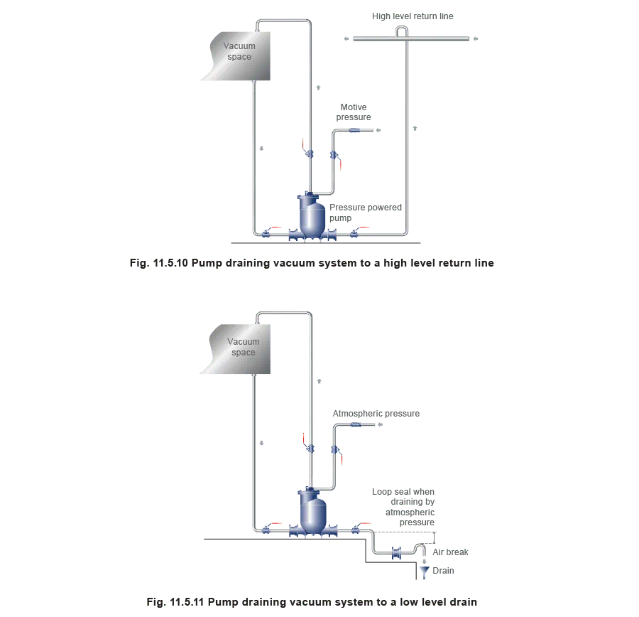
A soft seated check valve is recommended on the pump outlet where little or no lift is present, and an air break will act as an anti-syphoning device when draining to a point below the pump.
Atmospheric pressure can be used as the motive force when draining below the pump (Figure 11.5.11), but the outlet check valve should be positioned in a loop seal below the pump to induce a minimum opening head (dependant on the type of check valve) and water seal.
Should the pump be draining condensate from a vacuum gas system then compressed air or inert gas can be used as the motive force to drive the pump.
Steam trap drainage of temperature controlled processes
The steam trap is an automatic valve that relies on the system dynamics to provide flow. It has to rely on and react to external factors, such as steam pressure or static head pressure on the inlet side of the trap. The outlet pressure must be lower than the inlet pressure to provide flow in the correct direction. The rate of flow through any steam trap is therefore related to the differential pressure across it.
It is also possible to have negative differential pressures across the trap, which would promote reverse flow through it. When traps are installed to pass condensate into common return lines, it is advisable to fit non-return valves after each trap to prevent reverse flow under negative pressure conditions.
The occurrence of zero and negative differential pressure across steam traps is commonplace. The effects are commonly seen with temperature controlled processes i.e. heater batteries, calorifiers, jacketed pans, plate heat exchangers, in fact any process that has a control valve on the steam supply. It can occur irrespective of steam supply pressure, and depends wholly on the condensate system pressure and the steam pressure in the heat exchanger.
The term 'stall' describes this condition. Whenever it is predicted or diagnosed, another solution, such as a pump-trap is required to remove the condensate from the heat exchanger.
The phenomenon is discussed in greater detail in Block 13 - 'Condensate removal'.
Highlighted products
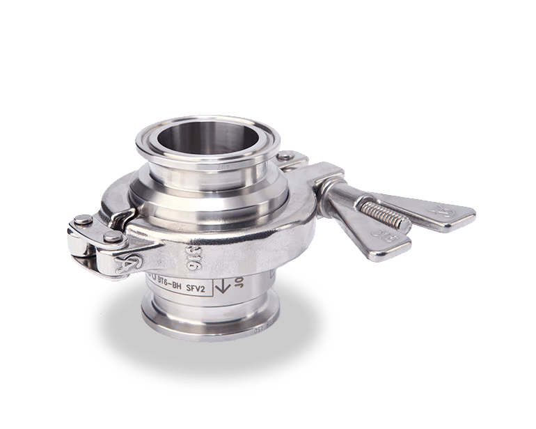
BT6 Balanced Pressure Steam Trap
The BT6 316L stainless steel balanced pressure steam trap is specifically designed for hygienic applications including steam barriers, CIP/SIP and process vessel drainage, sterilisers and autoclaves, and culinary steam mains drainage.
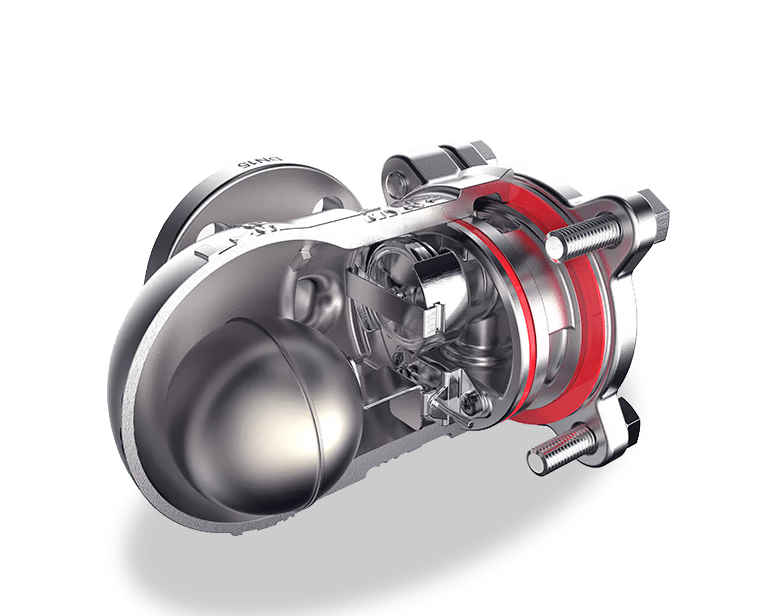
FTS14 Ball Float Steam Trap
The requirement for 316 stainless steel is gradually being extended to secondary side media such as steam and hot water.
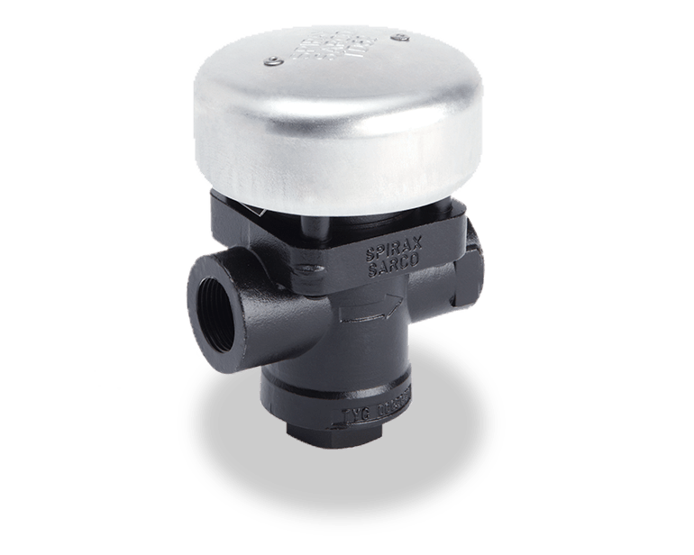
TD62M and TD62LM
The TD62LM and TD62M are maintainable high pressure thermodynamic steam traps with integral strainer and a replaceable seat to ease maintenance.